
Part 5—Pipe Heating Example
Part 5—Pipe Heating Example
This is part 5 of a 5 part series on modeling a fluid circuit using the Modelica Fluid library. Please go through the previous part, if you have not done it already:
In this post, I will model filling of a tank using a pipe that heats the fluid flowing through it.
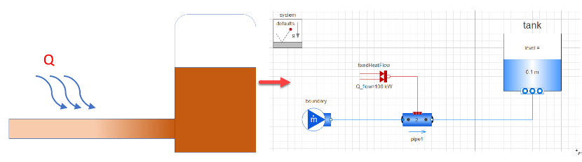
Model to determine the effect of heat addition on the fluid temperature.
Steps
Steps
◼
Create a new model
◼
Drag the following components from the Modelica standard library:
◼
Fluid.Vessels.OpenTank
◼
Fluid.System: Used to define system properties and default values so that you do not need to define it for every component
◼
Fluid.Sources.MassFlowSource_T: Used as a constant mass flow source
◼
Fluid.Pipes.DynamicPipe: It can store mass and energy
◼
Thermal.HeatTransfer.Sources.FixedHeatFlow: Used as a heat source
◼
Define the parameters of the tank:
◼
Medium (This parameter cannot be left blank)
◼
Select a fluid from the drop-down. Eg: “Extension of the standard water package”
◼
height
◼
Total height of the tank
◼
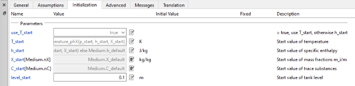
By default, the initial level of fluid in the tank is set at 0.5 * height of the tank. You can keep the default or change it by going to the Initialization tab changing the level_start parameter
◼
crossArea
◼
Define cross sectional area of the tank
◼
Ports (Important) : This refers to the outlet of the tank to which other components can be connected
◼
nPorts
◼
In this example as we want to connect only to the ambient we will set the nPorts to 1
◼
use_portsData
◼
set use_portsData to true
◼
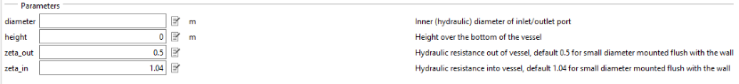
portsData
◼
Provide the portsData as a list which means they need to be specified using curly braces {}.
◼
It takes a function as an argument. The function is Modelica.Fluid.Vessels.BaseClasses.VesselPortsData().
◼
You can open the function (type the name in the search field in the Class Browser) and check the inputs
◼
You can define diameter, height and other parameters
◼
For our example we want to set the port height to 0 m and diameter to 0.3 m. We will use the defaults for zeta_out and zeta_in.
◼
The input to the portsData should look like this:
◼
{Modelica.Fluid.Vessels.BaseClasses.VesselPortsData(diameter = 0.3, height = 0)}

◼
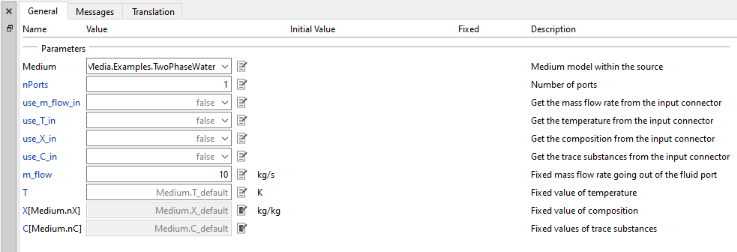
Define the parameters of the boundary:
◼
Medium
◼
Select a fluid from the drop-down. Eg: “Extension of the standard water package”
◼
nPorts
◼
As the boundary is only connected to the pipe, set this value to 1
◼
m_flow
◼
Provide a value for the mass flow rate
◼
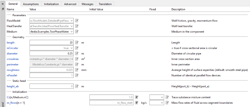
Define the parameters of the pipe:
◼
Medium (This parameter cannot be left blank)
◼
Select a fluid from the drop-down. Eg: “Extension of the standard water package”
◼
length
◼
Total length of the pipe
◼
isCircular
◼
You can chose between circular and non-circular
◼
If isCircular is set to false then crossArea and perimeter parameter have to be defined. Note that it is assumed that the cross-sectional area is constant throughout the length.
◼
diameter
◼
Diameter of the circular pipe
◼
roughness
◼
Roughness of the inner pipe surface
◼
This is a pipe material property, so common materials and their roughness values are listed below:
◼
PVC: 0.0015—0.007 mm
◼
Stainless steel: 0.001—0.006 mm
◼
Ordinary concrete: 0.3-1 mm
◼
Data was taken from this reference: https://www.engineeringtoolbox.com/surface-roughness-ventilation-ducts-d_209.html
◼
height_ab
◼
Difference in height between the outlet (port_b) and inlet (port_a). Check the arrow direction of the pipe to determine inlet and outlet.
◼
Assumptions tab
◼
Set use_HeatTransfer to true
◼
Define the parameters of the fixedHeatFlow:
◼
Q_flow
◼
Set a fixed heat flow rate
◼
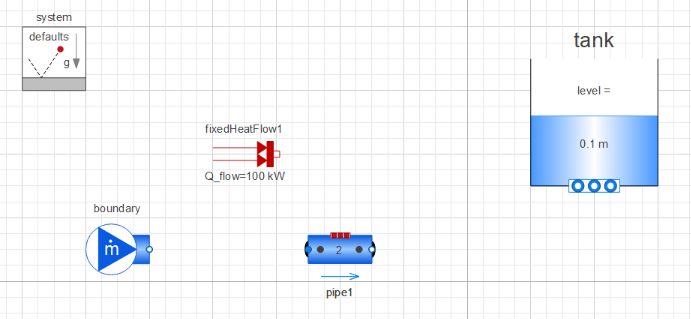
Connect the components as shown in the figure:
◼
Provide a simulation time in the Experiment Setup and simulate:
◼
Plot the temperature and level of the tank
◼
temperature can be obtained from the heat transfer data: tank.heatTransfer.Ts[1]
◼
level can be obtained by plotting the level: tank.level
◼
The temperature of the fluid inside the tank increases from 20°C to about 22°C after 100 minutes.
This ends the 5 part series on Getting Started with Fluid Circuits. You should now be able to instantitate basic components of the Modelica Fluid library like pipes, tanks, valves, pumps and fluid sources, and create your own fluid circuits.
Other posts in this series can be found here: