
Part 1—Tank Example
Part 1—Tank Example
In this post, we will model a tank that has an outlet to the ambient. Using this model, we will observe how the flow velocity changes with the height of the tank.
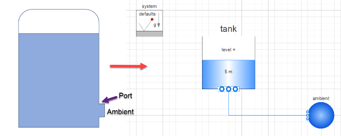
Model to determine the flow velocity at the tank outlet.
Steps
Steps
◼
Create a new model
◼
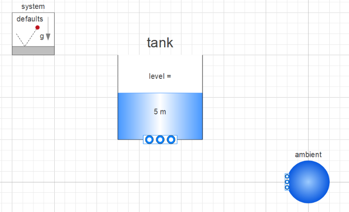
Drag the following components from the Modelica standard library:
◼
Fluid.Vessels.OpenTank
◼
Fluid.System: Used to define system properties and default values so that you do not need to define it for every component
◼
Sources.FixedBoundary: Used to define the pressure (boundary condition) at the outlet
◼
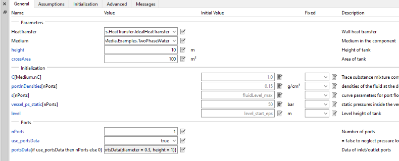
Define the parameters of the tank:
◼
Medium (This parameter cannot be left blank)
◼
Select a fluid from the drop-down. Eg: “Extension of the standard water package”
◼
height
◼
Total height of the tank
◼
By default, the initial level of fluid in the tank is set at 0.5 * height of the tank. You can keep the default or change it by going to the Initialization tab changing the level_start parameter
◼
crossArea
◼
Define cross sectional area of the tank
◼
Ports (Important) : This refers to the outlet of the tank to which other components can be connected
◼
nPorts
◼
In this example as we want to connect only to the ambient we will set the nPorts to 1
◼
use_portsData
◼
set use_portsData to true
◼
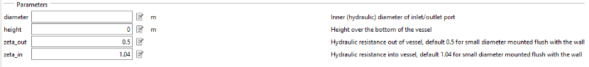
portsData
◼
Provide the portsData as a list which means they need to be specified using curly braces {}.
◼
It takes a function as an argument. The function is Modelica.Fluid.Vessels.BaseClasses.VesselPortsData().
◼
You can open the function (type the name in the search field in the Class Browser) and check the inputs
◼
You can define diameter, height and other parameters
◼
For our example we want to set the port height to 1 m and diameter to 0.3 m. We will use the defaults for zeta_out and zeta_in.
◼
The input to the portsData should look like this:
◼
{Modelica.Fluid.Vessels.BaseClasses.VesselPortsData(diameter = 0.3, height = 1)}
◼
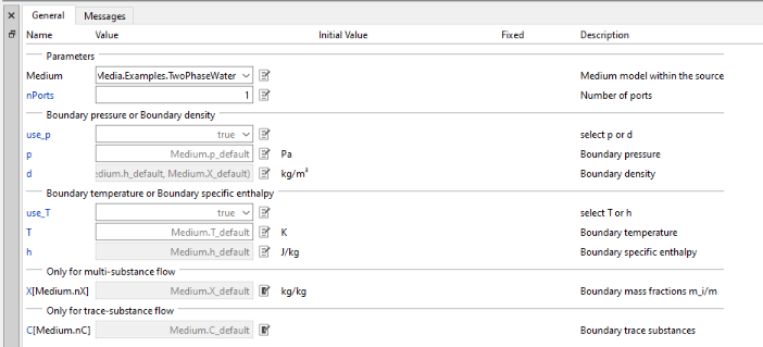
Define the parameters of the ambient:
◼
Medium
◼
Select a fluid from the drop-down. Eg: “Extension of the standard water package”
◼
nPorts
◼
As the ambient is only connected to the tank, set this value to 1
◼
Connect the ports of the tank and ambient:
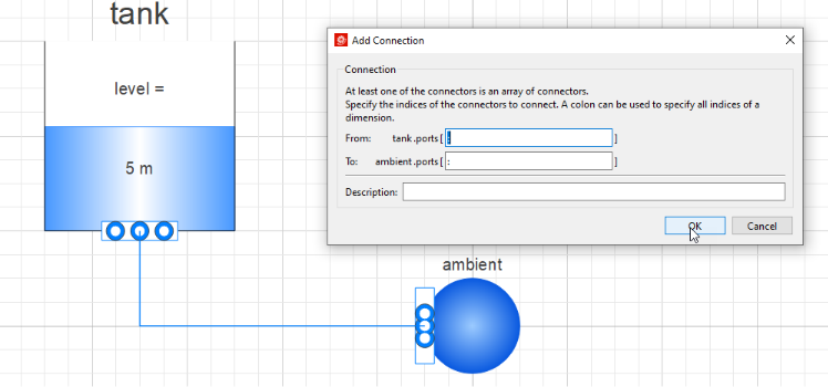
◼
Provide a simulation time in the Experiment Setup and simulate:
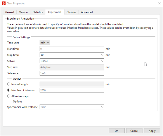
◼
Plot the mass flow rate and level at outlet in Simulation Center
◼
mass flow rate can be obtained from the ports data: tank.ports[1].m_flow
◼
level can be obtained by plotting the level: tank.level
◼
Negative mass flow rate shows that fluid is moving out of the tank. As the fluid level is decreasing the mass flow rate also decreases (moves towards zero).
In this post, we instantiated a tank and observed how the flow velocity changes with the height of the tank. In the next post, we will use a pipe and observe how the pipe parameters and flow properties like Reynolds number, material roughness etc contribute to the frictional head losses.
Other posts in this series can be found here: