In the last post, we examined how heat propagates within an electric vehicle (EV) battery and how uncertainty in temperature measurements can be incorporated into a system-level model.
Now, using these insights, we will construct a Battery Thermal Controller that effectively manages the temperature of an EV battery pack. This controller will ensure the battery operates within safe thermal limits, thereby improving its performance, safety, and longevity.
Where were we?
Where were we?
We had a model that incorporates spatial heat propagation dynamics, which are derived from finite element simulations, and integrates these into a simplified lumped model. By doing so, we could better capture the complexities of battery temperature behavior and address the uncertainties inherent in temperature measurements across the battery pack.
Understanding the Need for Thermal Control
Understanding the Need for Thermal Control
Thermal management is crucial for electric vehicles. Batteries operate optimally within a specific temperature range-typically between 25°C and 40°C. Exceeding this range can lead to diminished performance, reduced battery life, and even safety hazards.
A battery that runs too hot can experience thermal runaway, while a battery that is too cold can suffer from reduced power output.
A battery that runs too hot can experience thermal runaway, while a battery that is too cold can suffer from reduced power output.
Key question: How do we maintain the battery’s temperature within this range while accounting for real-time fluctuations in both environmental conditions and the battery’s internal heat generation?
The answer lies in an effective thermal control system, which we will now design using System Modeler.
Picking up from where we left of
Picking up from where we left of
We need to again import open source system model library that we have been adding our model developments during the journey . Let’s check the last model we created to capture the measurement uncertainties.
"EHPTlib.mo"
In[]:=
modelFileName=FileNameJoin[{NotebookDirectory[],"package.mo"}];modelLib=Import[modelFileName];model=SystemModel["EHPTlib.Examples.EV.EVwtUncertainties"];model["Diagram"]
Out[]=
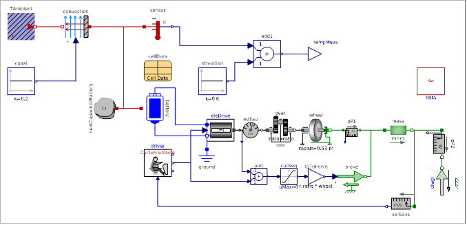
Here we see the comprehensive representation of the Tesla Model S structure, including its battery, drive system, and transmission components even the battery thermal convection.
Let’s upload FEM results to reiterate the measurement uncertainties.
In[]:=
Tfun=InterpolatingFunction
;
In[]:=
SystemModelUncertaintyPlot[model,<|"Outputs"->{"tempMeas"},"ParameterValues"->{"deviation.k"->QuantityDistribution[TruncatedDistribution[{0,Infinity},NormalDistribution[0,Mean[StandardDeviation[Tfun["ValuesOnGrid"]]]]],"Kelvins"]},"InterpolationPoints"->200,"SimulationInterval"->{0,10000}|>,PlotLabel->"Temperature measurement"]
Out[]=
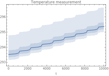
As we mentioned earlier, there is nothing preventing the battery temperature to increase unboundedly. Let’s design a battery thermal controller that averts the battery being overheated.
Designing the Battery Thermal Controller
Designing the Battery Thermal Controller
In reality, Tesla use quite an advanced system called Octovalve heat pump to regulate inside the whole car. For the sake of straightforwardness, I will focus on something simpler.
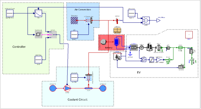
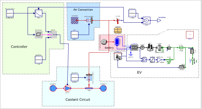
The Battery Thermal Controller model needs to be built using a combination of temperature sensors, a PID controller, and hysteresis logic, all orchestrated to manage the battery’s temperature dynamically. Here, we can see the intended design diagram.
If we break down the design:
Battery Heat Capacity: The heat capacity of the battery is an essential parameter. It dictates how much heat the battery can store before its temperature changes significantly. This parameter, combined with the cooling system, helps to regulate temperature effectively.
Temperature Sensor: To manage the temperature, the controller requires real-time feedback. A sensor continuously monitors the battery temperature, providing critical data for the controller.
PID Controller: The Proportional-Integral-Derivative (PID) controller compares the sensor’s measured temperature to a predefined setpoint (optimal temperature) and adjusts the cooling system accordingly. This helps to maintain the battery temperature close to the desired value.
While I couldn’t find the exact Tesla coolant mass flow rate in its Model S vehicles, we can estimate the range based on typical automotive cooling systems. In liquid-cooled systems like those in electric vehicles, the coolant mass flow rate typically ranges between 2 to 10 liters per minute (L/min), or 0.033 to 0.167 kg/s, depending on the specific conditions. These values are set as limits in the controller output.
While I couldn’t find the exact Tesla coolant mass flow rate in its Model S vehicles, we can estimate the range based on typical automotive cooling systems. In liquid-cooled systems like those in electric vehicles, the coolant mass flow rate typically ranges between 2 to 10 liters per minute (L/min), or 0.033 to 0.167 kg/s, depending on the specific conditions. These values are set as limits in the controller output.
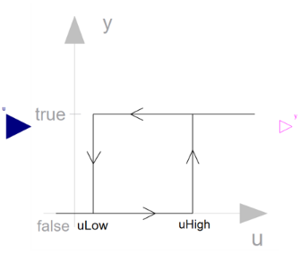
Hysteresis Control: To avoid the cooling system turning on and off frequently (which could lead to inefficiencies), we implement hysteresis control. This creates a buffer zone around the desired temperature, allowing the system to respond only when the temperature strays outside this zone.
Coolant Circuit: Glycol is chosen as working/coolant fluid. Since the battery is lumped, the convection calculations are lumped as well.
Q_flow = Gc*(batteryTemp - fluidTemp);Q_flow: Heat flow rate from 'battery' to 'fluid' (e.g., the glycol)Gc: Signal representing the convective thermal conductance in [W/K]
Gc is assumed to be 450 W/K meaning that each one degree difference will cause 450 W heat transfer from the battery to the glycol if the pump works at the maximum capacity.
Incorporating Uncertainty in Temperature Measurement
Incorporating Uncertainty in Temperature Measurement
As discussed in the previous blog, temperature measurements across a battery pack can vary due to spatial heat propagation. These variations arise because different areas of the battery heat up at different rates. In this controller design, we handle these uncertainties by incorporating statistical deviations into the system model.
These deviations were derived from earlier PDE-based heat transfer simulations. By modeling heat propagation across the battery body and applying statistical analysis to the results, we can more accurately predict how temperature will vary in real-world conditions.
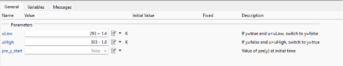
Incorporating these uncertainties into the controller design allows us to narrow down the hysteresis limits, enabling the system to more effectively manage sensor reading deviations and provide more reliable temperature control.
In[]:=
model=SystemModel["EHPTlib.Examples.EV.EVwController"];model["Diagram"]
Out[]=
Visualizing Some Simulation Results
Visualizing Some Simulation Results
Let’s explore the simulation outputs from the battery thermal management system under realistic driving conditions. The results provide us insight into how the thermal controller interacts with the battery’s dynamic power demands, temperature variations, and charge levels.
In[]:=
sim=SystemModelSimulate[model]
Out[]=
SystemModelSimulationData
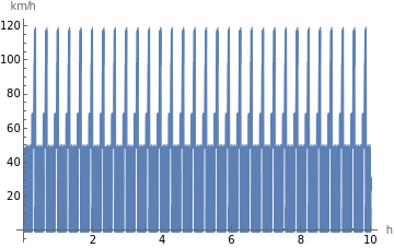
The first plot represents the vehicle’s speed over a 10-hour period (it may be long, however, to see dynamics we like it was needed), showcasing frequent shifts between approximately 40 km/h and peaks around 120 km/h. This high-frequency acceleration-deceleration pattern simulates the demands of urban driving or standardized driving cycles, which include intervals of acceleration and braking. Such speed fluctuations are critical in evaluating the battery thermal management system, as they mimic real-world conditions that place varying thermal loads on the battery pack.
In[]:=
SystemModelPlot[sim,"Vehicle speed",ImageSize->Medium,PlotRange->Full]
Out[]=
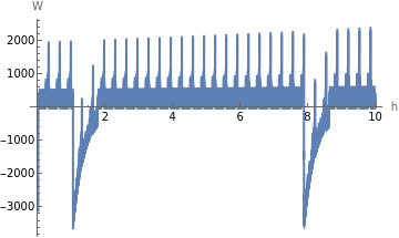
In the second plot, we see the battery heat flow of the EV during the simulation. Positive spikes indicate heat flowing into the battery during acceleration, where it goes up to 2000 watts, while the deep troughs reflect thermal management system kicking in, reaching down to -3000 watts.
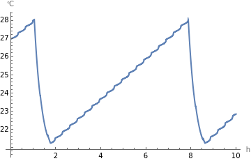
If we want to observe how the battery temperature fluctuates over time, rising during periods of high power demand and cooling during low-demand phases. The temperature oscillates between 22°C and 28°C, indicating that the thermal management system is successfully keeping the battery within a safe operating range we set above despite the cyclic thermal load. This control is crucial in maintaining battery performance and lifespan, as excessive heating could degrade the battery, while too much cooling could impact efficiency.
In[]:=
SystemModelPlot[sim,#,ImageSize->Medium,PlotRange->Full]&/@{"battery.heatPort.T","battery.SOC"}//Column
Out[]=
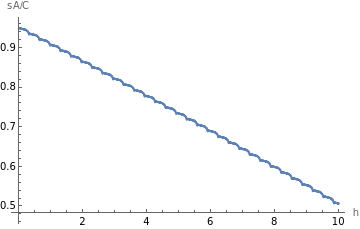
The SOC graph displays a gradual decline from 0.9 to about 0.5 over the simulation period, showing battery depletion under continuous use. Minor fluctuations in SOC align with regenerative braking events, where the battery temporarily gains charge. Monitoring SOC alongside temperature provides a comprehensive view of battery health and performance.
Conclusion
Conclusion
By combining the insights from PDE-based heat propagation simulations with a dynamic PID controller and hysteresis logic, we’ve developed a robust Battery Thermal Controller that can effectively manage the temperature of an electric vehicle battery. The integration of uncertainty into the model ensures that the controller can handle real-world temperature variations, resulting in a more reliable and efficient thermal management system.
This design marks an important step in optimizing battery performance and safety in electric vehicles, ensuring that the thermal behavior of the battery is well-regulated, even under the most demanding conditions.
CITE THIS NOTEBOOK
CITE THIS NOTEBOOK
Electrical vehicle insights: battery management system — temperature control
by Vedat Senol
Wolfram Community, STAFF PICKS, October 28, 2024
https://community.wolfram.com/groups/-/m/t/3308846
by Vedat Senol
Wolfram Community, STAFF PICKS, October 28, 2024
https://community.wolfram.com/groups/-/m/t/3308846