ABSTRACT (original article): We present an origami construction of a large-wing crane as an application of folding using virtual cutting and gluing of the edges of origami faces in the e-origami environment. Our methodology, based on a new cut-and-glue technique, allows us to detail the construction algorithm in classical origami through well-defined, incremental finely-tuned steps. We utilize a new origami model, as described in our earlier paper (T. Ida and H. Takahashi, 2020), and have developed software that implements several familiar classical origami folds. CITATION (original article): Tetsuo Ida, An e-origami artwork of a big wing crane, The 10th International Symposium on Symbolic Computation in Software Science, August 28–30, 2024. https://ceur-ws.org/Vol-3754/
Full Article: https://ceur-ws.org/Vol-3754/paper07.pdf
Full Article: https://ceur-ws.org/Vol-3754/paper07.pdf
Keywords e-origami, classical fold, paper folding rule, cut-and-glue technique.
Introduction
Introduction
An origami artwork consists of an arrangement of bounded planes, with two surfaces or faces intricately connected and layered through repeated folds of a single (virtual) sheet of paper. This collection of faces culminates in an object with remarkable characteristics. In this post, we demonstrate that cutting the edges of faces reveals a new combination of classical folds. By gluing the separated faces back together, we restore their connection. This cut-and-glue technique, which we introduced in our previous articles[1, 2], opens up possibilities, allowing the discovery of new folds previously considered impossible using Huzita-Justin folds [3, 4], which have limitations when applied to practical constructions. For instance, the inside reverse fold—one of the most versatile yet straightforward classical folds—cannot be achieved with Huzita-Justin folds alone. However, by applying the cut-and-glue technique, we can realize the inside reverse fold by combining valley and mountain folds, which is fundamentally the dsmr as one of the Huzita-Justin folds.
We show the practical application of our method by constructing a large-wing crane, a sophisticated origami structure that warrants thorough research investigation [3].
Modeling for e-origami
Modeling for e-origami
Origami is now an internationally recognized term, meaning "folding paper." It also refers to the practice of folding origami. We use the word "origami" as a countable noun for the former use. We can construct objects of interesting shapes when we freely choose fold lines and allow overlaps of faces without breaking the original sheet.
When we impose mathematically plausible fold line construction rules, we can define an origami geometry that deserves deep mathematical investigation. Euclidean plane geometry constructs geometrical objects using only a straightedge and a compass. Similarly, origami geometry, a tool-less approach, defines its rules. Huzita-Justin's rules are the commonly agreed rule set based on superposition of lines and points. Table 1 lists the four (out of seven) Huzita-Justin rules that we will use to construct a large-wing crane. For the full details of the seven rules, see monograph [6]. These rules, together with newly implemented classical folds (see the section on Classical folds) and software tools of Eos[8,10], allow us to manipulate origami flexibly.
We now give a mathematical notation for the definition of origami and reason about its properties. In origami, we have faces and two kinds of neighborhood relations, superposition and adjacency, between the faces. A face is a convex polygon having an attribute of surface. When we denote polygon 𝑃1 ...𝑃𝑛, where we arrange points 𝑃1 ...𝑃𝑛 counterclockwise, we call the plane front surface, and the polygon 𝑃𝑛 ...𝑃1 is identified the same as with polygon 𝑃1 ...𝑃𝑛 with the attribute of the back surface.
We let Π be a finite set of faces,∽ be a binary adjacency relation on Π,
and ≻ be a binary superposition relation on Π. An abstract origami is a structure (Π,∽,≻). We abbreviate abstract origami to AO. We denote the set of AOs by O. An abstract origami system is an abstract rewriting system (O,↬) [7], where ↬ is a rewrite relation on O, called abstract fold. For 𝒪,(∈ O), we write 𝒪 ↬ when 𝒪 is abstractly folded to . We begin an origami construction with an initial AO and perform an abstract fold repeatedly until we obtain the desired AO.
and ≻ be a binary superposition relation on Π. An abstract origami is a structure (Π,∽,≻). We abbreviate abstract origami to AO. We denote the set of AOs by O. An abstract origami system is an abstract rewriting system (O,↬) [7], where ↬ is a rewrite relation on O, called abstract fold. For 𝒪,
𝒪
𝒪
𝒪
Usually, we start an origami construction with a square sheet of paper. This initial sheet of paper is abstracted as a face denoted by the numeral 1. Then, the initial AO 𝒪1 is represented by ({1},∅,∅). Furthermore, when we fold face 𝑛, the face is divided into two new faces: 2n and 2𝑛+ 1. We use this convention in this paper and in the Eos data structures [10]. Suppose that we are at the beginning of step 𝑖 of the construction, having AO 𝒪𝑖−1 = (Π𝑖−1,∽𝑖−1,≻𝑖−1). We perform an abstract fold and obtain a next AO 𝒪𝑖 = (Π𝑖,∽𝑖,≻𝑖). Thus, we have the ↬-sequence: 𝒪1 ↬ 𝒪2 ↬··· ↬ . An abstract origami construction is a finite ↬-sequence of AOs. In concrete terms, the operation ↬ can be a fold by one of Huzita-Justin rules, a mountain fold, a valley fold, etc., each requiring arguments of different kinds. We abuse 𝒪𝑖 to denote the origami constructed at step 𝑖.
𝒪
n
Table 1: Huzita-Justin rules
RuleCommandOperation
(O1)HO[PQ]FoldalonglinePQ(O2)HO[P,Q]FoldtosuperposepointPandpointQ(O3)HO[PQ,RS]FoldtosuperposelinePQandlineRS(O4)HO[PQ,X]FoldalongtheperpendiculartolinePQthatpassesthroughpointX
Classical folds
Classical folds
Mountain fold and Valley fold
Mountain fold and Valley fold
Understanding the fundamental operations of mountain and valley folds is essential in origami, as they dictate the folding orientation of the related faces. Folding an origami along a fold line and unfolding the fold to the previous shape leaves a line segment, called a crease, on the origami. These creases resemble a mountain ridge (mountain fold) and a valley lap (valley fold). The unfolding operation forms a crease after executing the mountain or valley fold. The result of the valley fold is illustrated in Fig. 1(b). At this step, the origami has two layers; however, the back layer is not visible because the upper triangular face completely overlaps the lower triangular face.
Next, we unfold the origami, as shown in Fig. 1(c). It is important to note that “unfold” does not mean simply “undoing.” We restore the origami to the previous shape depicted in Fig. 1(a), except for the dotted line segment CA, the valley crease. We see that the restored plane has two faces, 3 and 2: face 3 is to the right of CA.


Figure 1: Valley fold along CA and unfold
Similarly, we have a mountain fold below; if we fold the origami in Fig. 2 (a) along CA to bring the triangle ADC below ABC, we complete the mountain fold along CA. Unfolding the origami Fig. 2 (b), we restore the shape with mountain crease AC.


Figure 2: Mountain fold along CA and unfold
The mountain and valley folds resemble the Huzita-Justin rule (O1). While rule (O1) operates on all the stacked faces, mountain and valley folds are applied to user-selected faces. Huzita-Justin’s rules were conceived for plane geometry, comparing with Euclidean axioms devised for the plane geometry. We extend the Huzita-Justin rules to multiple plane layers.
FO
FO
The above observation on mountain and valley folds led us to define command FO. FO, standing for Fold Origami, is a command FO[θ][faces, ray] for rotating target faces along ray by angle θ. Using FO, we could define ValleyFold and MountainFold as FO[-π] and FO[π], respectively. With θ other than ± π, the application of FO results in a 3D origami. Usually, we use FO[θ] towards the steps of completing a construction.
Inside reverse and outside reverse folds
Inside reverse and outside reverse folds
The inside reverse and outside reverse folds are often employed in origami. Both work on a pair of superposed and adjacent faces. When the cut and glue technique is introduced, both folds are realized by combinations of the valley and mountain folds. However, each uses the valley and mountain folds on opposite faces.
First, we will show a simple example of an inside reverse fold. Let be a construction sequence for an inside reverse fold. Figure 3 shows the graphical representation of origami , , , and .
𝒪1𝒪4𝒪6↬𝒪7↬𝒪8
*
↬
*
↬
𝒪
1
𝒪
4,
𝒪
6
𝒪
7
𝒪
8


𝒪
1
𝒪
4
𝒪
6


Fig.3 (d) Fig.3 (e) Fig.3 (f) of wider gap
𝒪
7
𝒪
8
𝒪
8
Figure 3: InsideReverseFold
Origami is constructed from by a sequence of commands: ValleyFold, ValleyFold, and Unfold. It is a double-layer stack of faces. On the top layer are two faces, i.e., faces CFE and AEFD. On the second layer, i.e., the bottom layer, are two faces of the same shapes as the ones above but in opposite orientations. Each face is identified by a unique numeral called face ID, which is automatically assigned by the system. In this elementary example, we do not have to bother about the face IDs since it is unnecessary to specify to which faces we apply the inside reverse fold. For example, of Fig. 3(b), we simply apply the following command:
𝒪
4
𝒪
1
𝒪
4
InsideReverseFold[“CE”,“FE”]
The first argument, CE, specifies the edge to be cut. It is a character string denoting a segment and is interpreted as the type segment. The second argument, FE, is the ray along which mountain and valley folds are performed during command InsideReverseFold execution. The InsideReverseFold command performs the following operations:
1
. Check if the inside reverse fold is feasible. Namely, check if ∠CEF ≤𝜋/2. If true, proceed to step 2; otherwise abandon this command execution.
2
.Cut the edge CE. As a result, point C is split into C and C1(not visible). The result is 𝒪5 . Origami 𝒪5 is not shown in Fig. 3.
3
.Valley fold along ray FE. The face C1EG is moved. We impose a rule that faces to the right of a fold line (interpreted as a ray) are moved by a fold. The resulting origami is .
𝒪
6
4
.Mountain fold along ray FE. The face CFE is pushed. The result is 𝒪7.
5
.Glue the moved edges CE and C1E to form a new edge CE. The result is 𝒪8.
Performing steps 2 and 3 in sequence is possible when we cut and separate the shared edge CE. As we construct origami in a virtual space, we can cut CE and glue the moved CE and C1E without complication. After following the above steps, the obtained origami is shown in Fig. 3(e) and (f), illustrating the origami object's ins and outs. In the case of the outside reverse fold, we make a polygonal cover on the faces.
An outside reverse fold differs from an inside reverse fold in that an outside reverse fold applies mountain and valley folds to different faces in opposite layers. We refer to the construction ,
where 𝒪𝑖,𝑖= 1,...,8 are visualized in Fig.4(a)∼(e). We apply the following command:
𝒪1𝒪4𝒪6↬𝒪7↬𝒪8
*
↬
*
↬
where 𝒪𝑖,𝑖= 1,...,8 are visualized in Fig.4(a)∼(e). We apply the following command:
OutsideReverseFold["CE","FE"]
to , and obtain . Note that constraint 𝜋/2 ≤∠𝐶𝐸𝐹 ≤𝜋 should be satisfied. The origami construction sequence in Fig.4 is now self-explanatory. Figure 4 (f) shows the origami structure of more clearly.
𝒪
4
𝒪
8
𝒪
8


Fig. 4 (a) Fig. 4 (b) Fig.4 (c)
𝒪
1
𝒪
4
𝒪
6


Fig. 4 (d) Fig. 4 (e) Fig.4 (f) of wider gap
𝒪
7
𝒪
8
𝒪
8
Figure 4: Outside reverse fold
Other classical folds
Other classical folds
In addition to the classical folds we have discussed so far, we analyzed the folding algorithms of the following classical folds well-known in the origami community, and implemented them: SquashFold, RabbitEarFold, SwivelFold, InsideCrimpPleatFold, and OutsideCrimpPleatFold, using the cut-and-glue technique. They are given in Figs. 5 - 9.
Out[]=


Figure 5: Squash fold
Out[]=


Figure 6: Inside crimp pleat fold
Out[]=


Figure 7: Outside crimp pleat fold
Out[]=


Figure 8: Rabbit ear fold
Out[]=


Figure 9: Swivel fold
Construction of a large-wing crane
Construction of a large-wing crane
We recommend that readers check the program code of the next section while reading this section.
Overview
Overview
In this construction, we start with a textually patterned initial face. Texture adds an artistic dimension to origami and makes it easier to distinguish face layers. This approach, requiring a special texture mapping algorithm, opens up new creative possibilities in origami modeling.
To complete the artwork shown below, we need 71 steps. In one step, an origami object, i.e., the computational realization of an abstract origami, will make one structural change. For example, we count one structural change of the origami object in one application of a valley fold, a mountain fold, and one of the Huzita-Justin folds. One inside reverse fold requires four sub-steps, i.e., cut, valley fold, mountain fold, and glue. The number of steps for the entire construction is surprisingly large at first sight, but we should observe that the origami objects have several symmetries. Therefore, a similar code sequence is repeated more than once. The number of crucial operations is limited.
The construction consists of the following four collections of steps.
(1) bird-base construction, (2) leg construction, (3) bill construction, and (4) wing construction. Let us examine the steps in each collection. Note that in all the steps, the graphics outputs below the line “large-wing crane/ori step: i “ is the visualization of.
To complete the artwork shown below, we need 71 steps. In one step, an origami object, i.e., the computational realization of an abstract origami, will make one structural change. For example, we count one structural change of the origami object in one application of a valley fold, a mountain fold, and one of the Huzita-Justin folds. One inside reverse fold requires four sub-steps, i.e., cut, valley fold, mountain fold, and glue. The number of steps for the entire construction is surprisingly large at first sight, but we should observe that the origami objects have several symmetries. Therefore, a similar code sequence is repeated more than once. The number of crucial operations is limited.
The construction consists of the following four collections of steps.
(1) bird-base construction, (2) leg construction, (3) bill construction, and (4) wing construction. Let us examine the steps in each collection. Note that in all the steps, the graphics outputs below the line “large-wing crane/ori step: i “ is the visualization of
𝒪
i
Bird-base construction
Bird-base construction
Let 𝜏 be a construction , where 𝑘 > 1 and has a specific distinguished feature 𝒜, we call 𝜏 an 𝒜-base construction. We also call an 𝒜-base. From 𝒜-base, we can further develop various origami artworks. We want to construct first a bird body-like origami in this application. In this case, 𝒜 is “bird.”
𝒪
1
*
↬
𝒪
k
𝒪
k
𝒪
k
𝒪
k
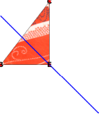
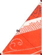
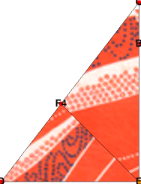
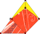
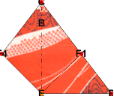
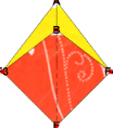
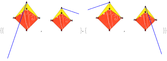
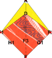
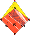
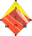
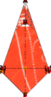
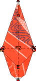
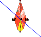
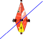
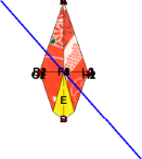
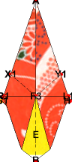
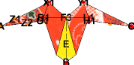
We now refer to the program in the program section. We start with an initial origami of a rhombus shape to make the crane’s wings larger than the crane made from the square initial origami. Applying (O2) to and , we obtain . is quad-layered. We apply rule (O3) to fold along the bisector of ∠BEC, and then unfold to obtain . Steps 4 and 5 aim to construct a crease F4E that will be used in the inside reverse fold on . has three other creases, F3E, F2E, and F1E, at the intersection of the bisector and the hypotenuses of the right triangular faces on the inner layers.
𝒪
1
𝒪
1
𝒪
2
𝒪
3
𝒪
3
𝒪
3
𝒪
4
𝒪
5
𝒪
5
Origami
𝒪
5
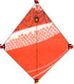
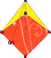
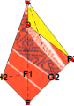
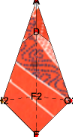
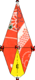
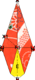
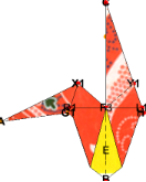
The subsequence of the construction shows the first application of the inside reverse fold on . InsideReverseFold[BE, F4E] performs four sub-steps, i.e., cut, valley fold, mountain fold, and glue, and returns . The top view of and may look similar. However, after closer inspection, we recognize the texture patterns of the surfaces are different.Two triangular faces BF3E and BF4E have been moved below face CEF4 in . Applying ValleyFold to the top layer yields . By turning over , we have origami .
𝒪
5
*
↬
𝒪
9
𝒪
5
𝒪
9
𝒪
5
𝒪
9
𝒪
9
𝒪
10
𝒪
10
𝒪
11
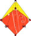
Similarly, we apply another inside reverse fold and valley fold to the right half of , and obtain the construction sequence ↬.
𝒪
11
𝒪
11
*
↬
𝒪
15
𝒪
16
The rest of the sequence 𝜏 is fully described in the program section. Since the shape of is symmetric with respect to the axis AE, we simulate the simultaneous constructions on the right and left of the axis using the higher-order operators Composition and @@@ (MapApply) of the Wolfram Language[8].
𝒪
17
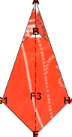
At the end of the bird-base construction, we obtain the bird-base . The bird- base is crucial in origami crane construction, whether for the large-wing crane or for a commonly known classical crane. This slim diamond-shape origami piece has a crack in the middle of the upper half. This piece is quad-layered, and symmetric with respect to the vertical axis AB.
𝒪
49
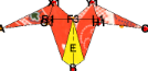
Leg construction
Leg construction
The leg construction sub-sequence is , where we perform the inside reverse fold to the right and left parts of the bird-base. Note that the inside reverse fold can be applied to multiple layers of faces. In this case, four layers are involved in each execution of the inside reverse fold.The moved faces become the legs of the crane.
𝒪
49
*
↬
𝒪
61
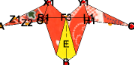
Bill construction
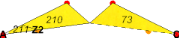
Bill construction
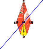
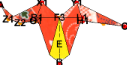
The bill construction sub-sequence is . Here, we make crease Z1Z2, where we choose by the designer’s preference arbitrary positions of points Z1 and Z2 on the edges. Command NewPointBetween is used to construct points Z1 and Z2 exactly on each edge of the faces. The crease determines the twist of the bill. We perform the inside reverse fold on . Then, we rotate along R1L1 by 𝜋 and obtain .
𝒪
62
*
↬
𝒪
68
𝒪
63
𝒪
67
𝒪
67
Wing construction
Wing construction
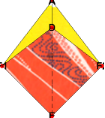
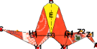
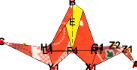
We first make the shape of the wings triangular. Finally, we apply the command FO twice to make the origami three-dimensional. We apply FO[(-7/16) 𝜋] on two sets of the faces that constitute the wings. We complete the construction to bring the bill to the right, as this is our intended posture. The final origami is .
𝒪
77
Program of the construction
Program of the construction
Session: large-wing crane
Session: large-wing crane
We will define a new Eos session called “large-wing crane."
In[]:=
EosSession["large-wing crane"];
Bird-base
Bird-base
In[]:=
ht::usage="Variable ht specifies the ratio of the two diagonals, horizontal and vertical, of a rhombus.";
In[]:=
ht=1.3;
In[]:=
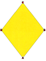
With[{rhombus=Polygon[5.0*{{1,0},{2,ht},{1,2ht},{0,ht}}]},NewOrigami[rhombus]]
large-wing crane/Ori: Step 1
Out[]=
In[]:=
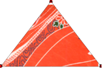
HO["A","C"]
large-wing crane/Ori: Step 2
In[]:=
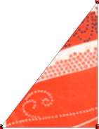
HO["B","D",Mark->{{"DB","E"}}]
large-wing crane/Ori: Step 3
In[]:=
HO["EC","EB"]
large-wing crane/Ori: Step 3
,
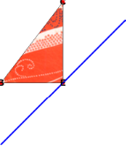
We have two fold lines that superpose lines EC and EB, we have to choose the one that suits our purpose, i.e., the second fold line above. The graphics are ordered according to the slope of the involved fold line. Therefore, the following code is immediate without looking at the above output. The above code id unnecessary, actually. The last symbol ! is a postfix operator of Unfold.
In[]:=
HO["EC","EB",FoldLine->2,Mark->{{"BC","F4","F3","F2","F1"}}]!
large-wing crane/Ori: Step 5
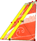
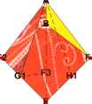
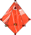
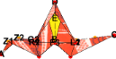
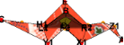
We check inner layers of the origami and face connections by command ShowLayers. Rotate the graphics to see the sharing of the edges.
In[]:=
ShowLayers[Gap->1,Hinge->True,HingeColor->{Yellow,Red}]
large-wing crane/Ori: Step 5
Out[]=
We apply InsideReverseFold on F4E.
In[]:=
InsideReverseFold["BE","F4E"]
large-wing crane/Ori: Step 9
Out[]=
In[]:=
ValleyFold[$Top,"CE"]
large-wing crane/Ori: Step 10
Out[]=
In[]:=
TurnOver[](*tobacksurface*)
large-wing crane/Ori: Step 11
Out[]=
We apply Inside reverse fold on EF1.
In[]:=
InsideReverseFold["ED","EF1"]
large-wing crane/Ori: Step 15
Out[]=
In[]:=
ValleyFold[$Top,"EC"]
large-wing crane/Ori: Step 16
Out[]=
In[]:=
TurnOver[](*tofrontsurface*)
large-wing crane/Ori: Step 17
Out[]=
In[]:=
HO@@@{{"AF3","AE"},{"AF4","AE"}}
large-wing crane/Ori: Step 17
Out[]=
In[]:=
Composition[Unfold,HO]@@@{{"AF3","AE",FoldLine->1,Mark->{{"F3E","G1"}},By->"F3"},{"AF4","AE",FoldLine->2,Mark->{{"F4E","H1"}},By->"F4"}}
large-wing crane/Ori: Step 21
,
In[]:=
InsideReverseFold@@@{{"F3G1","AG1"},{"H1F4","H1A"}}
large-wing crane/Ori: Step 29
,
In[]:=
TurnOver[](*tobacksurface*)
large-wing crane/Ori: Step 30
Out[]=
In[]:=
Composition[Unfold,HO]@@@{{"AF1","AE",FoldLine->1,Mark->{{"F1E","H2"}},By->"F1"},{"AF2","AE",FoldLine->2,Mark->{{"F2E","G2"}},By->"F2"}}
large-wing crane/Ori: Step 34
,
In[]:=
InsideReverseFold@@@{{"F1H2","CH2"},{"G2F2","G2C"}}
large-wing crane/Ori: Step 42
In[]:=
,
In[]:=
TurnOver[](*tofrontsurface*)
large-wing crane/Ori: Step 43
Out[]=
In[]:=
HO["AE","F3",By->"E",Mark->{{"AG1","R1","$Ra","$Rb","R2"},{"AH1","L1","$La","$Lb","L2"}}]!
large-wing crane/Ori: Step 45
Out[]=
In[]:=
Composition[TurnOver,HO]@@@{{"L1R1",By->"B"},{"L2R2",By->"D"}}
large-wing crane/Ori: Step 49
,
Leg
Leg
We have four layers and form two pairs of faces. Moreover, it is nontrivial to identify the mutual relations of the faces. To see these relations among involved faces, we use the command ShowFaces, and carefully examine the displayed faces at each level, which are to be passed to the command InsertReverseFold. When four faces {f1,f2,f3,f4} are involved, where f1 and f4 had shared edge XY, instead of XY as the first argument for cut, we specify {XY,{{f1, f2},{f3,f4}}}.
In[]:=
HO@@@{{"AF3","G1F3",ShowOverlappingPointsTrue},{"AF3","H1F3",ShowOverlappingPointsTrue}}
large-wing crane/Ori: Step 49
,
,
,
In[]:=
Composition[Unfold,HO]@@@{{"AF3","G1F3",By->"A",FoldLine->2,Mark->{{"AG1","X1","$Xa"}}},{"AF3","H1F3",By->"C",FoldLine->1,Mark->{{"AH1","Y1","$Ya"}}}}
large-wing crane/Ori: Step 53
,
In[]:=
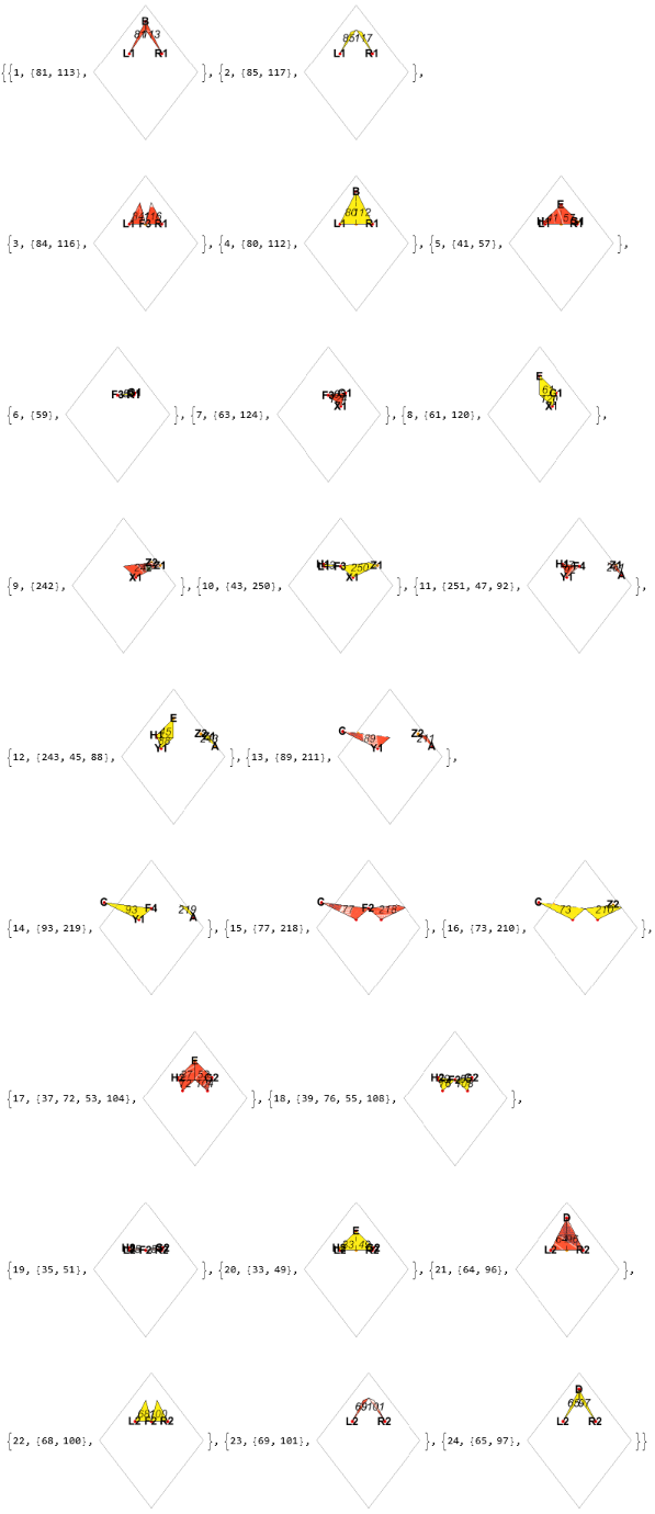
Block[{$showFaces=True},ShowFaces[ImageSize->100]]
large-wing crane/Ori: Step 53
1,{42,58},
,2,{40,56},
,3,{41,57},
,{4,{43,59},
},5,{47,92,93,63,124,125},
,6,{45,88,89,61,120,121},
,7,{37,72,73,53,104,105},
,8,{39,76,77,55,108,109},
,{9,{35,51},
},10,{33,49},
,11,{32,48},
,12,{34,50},
In[]:=
InsideReverseFold@@@{{{"F3A",{{109,105},{121,125}}},"F3X1"},{{"CF3",{{77,73},{89,93}}},"Y1F3"}}
large-wing crane/Ori: Step 61
,
Bill
Bill
In[]:=
billRatio::usage="bill ratio defines the bending point of the leg, where the bill part starts. It should be between 0 and 1.";
In[]:=
billRatio=0.7;
In[]:=
NewPointBetween["Z1"->{billRatio,{"X1","A"}}]
large-wing crane/Ori: Step 61
In[]:=

In[]:=
NewPointBetween["Z2"->{billRatio-0.1,{"F3","A"}}]
large-wing crane/Ori: Step 61
Out[]=
In[]:=
ValleyFold[{109},"Z1Z2"]!
large-wing crane/Ori: Step 63
Out[]=
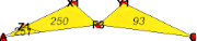
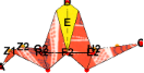
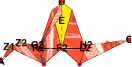
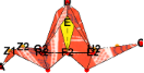
layers=With[{faces=Block[{$showFaces=True},ShowFaces[]]},faces//Print;Second/@faces];
large-wing crane/Ori: Step 63
1,{42,58},
,2,{40,56},

,3,{41,57},

,{4,{43,59},

},5,{47,92,63,124},

,6,{45,88,61,120},

,7,{89,242,243},

,8,{93,250,251},
,9,{77,218,219},
,10,{73,210,211},

,11,{37,72,53,104},
,12,{39,76,55,108},

,{13,{35,51},

},14,{33,49},

,15,{32,48},

,16,{34,50},


Since we have seen that left the leg in the above image consists of the 7th, 8th, 9th,and 10th layers, we extract those layers, and then the faces that are parts of the bill.
billlayers=Last/@Part[layers,{10,9,8,7}];
large-wing crane/Ori: Step 63
In[]:=
billPair=Partition[billlayers,2]
large-wing crane/Ori: Step 63
Out[]=
{{211,219},{251,243}}
In[]:=
InsideReverseFold[{"AZ1",billPair},"Z1Z2"]
large-wing crane/Ori: Step 67
Out[]=
In[]:=
TurnOver["R1L1"](*Upside-downandturnovertoback*)
large-wing crane/Ori: Step 68
Out[]=
Wing
Wing
We need to find faces to rotate .
In[]:=
Block[{$showFaces=True},ShowFaces[ShowFrame->True,Level->{1,2}]]
large-wing crane/Ori: Step 68
1,{34,50},
,2,{32,48},


We make both wings triangular shapes.
In[]:=
ValleyFold@@@{{{50,48},"DR2"},{{34,32},"L2D"}}
large-wing crane/Ori: Step 70
,
In[]:=
TurnOver[]
large-wing crane/Ori: Step 71
Out[]=
In[]:=
ValleyFold@@@{{{42,40},"BL1"},{{58,56},"R1B"}}
large-wing crane/Ori: Step 73
,
In[]:=
Block[{$showFaces=True},ShowFaces[ImageSize->100,Frame->True,ShowFrame->True]]
large-wing crane/Ori: Step 73
Out[]=
$tolerance=1.010^(-3);(*Chop[_,$tolerance]*)
In[]:=
wingRotationAngle=(7/16)π;
In[]:=
Composition[TurnOver,FO[-wingRotationAngle]]@@@{{{80,112},"R1L1"},{{64,96},"L2R2"}}
large-wing crane/Ori: Step 77
,
In[]:=
final=ShowOrigami[ShowFrame->False,Gap->0.008,ImageSize->300,MarkPoints->{},Lighting->"Automatic"]
large-wing crane/Ori: Step 77
Out[]=

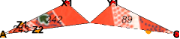
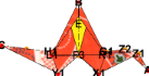
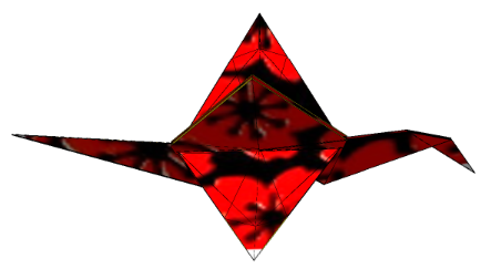
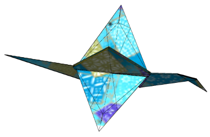
Textured origami
Textured origami
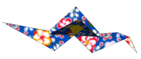
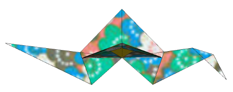
We show several other textured artworks of the large-wing crane. They are obtained by adding different textures to the graphics image of , using the functionality of texture mapping of Mathematica 14.1.0. Command Chiyogami[] gives the collection of Chiyogami graphics provided by Eos. We use Chiyogami 3, 9 and, 12.
𝒪
77
In[]:=
Chiyogami[]
large-wing crane/Ori: Step 77
Out[]=
1
,2
,3
,4
,5
,6
,7
,8
,9
,10
,11
,12
,13
,14
,15
,16
,17
,18
,19
Do[SetOptions[ShowOrigami,Lighting"Neutral",FrameFalse,TextureChiyogami[i][]];final2=ShowOrigami[ShowFrame->False,Gap->0.008,ImageSize->300,MarkPoints->{}];Print[final2],{i,{3,9,12}}];
Concluding remarks
Concluding remarks
We have shown that the cut-and-glue technique simplifies modeling the classical folds and, hence, the implementation of their algorithms in the e-origami environment. Using a cut operation, we have shown that the seemingly complex inside (and outside) reverse fold is reduced to a sequence of the classical elementary folds valley fold and mountain fold. We have also shown other popular classical folds, such as rabbit ear folds.
We constructed a large-wing crane origami as a nontrivial application of the newly defined inside reverse fold. The design is coordinate-free yet allows for the freedom of choice of wing angles and two positions of bending points of a bill. The construction proceeds as step-by-step fold operations, observing the symmetries of origami objects constructed on the way. The construction is described in the Orikoto origami programming language. Thus, creating a large-wing crane is purely an algorithmic process. Furthermore, the added feature of texture mapping to Eos makes the final product more original artwork.
The algorithm’s implementation in the earlier articles [1, 2] was extensively tested and extended for more capabilities. The package Eos, currently version 3.8.2, is implemented in Mathematica 14.1.0. It is available to Mathematica programmers on the site https://www.i-ros.org when requested to admin@i-eos.org.
Initialization Cells
Initialization Cells
References
References
1
.T. Ida, H. Takahashi, A new modeling of classical folds in computational origami, in: P. Janičić, Z. Kovács (Eds.), Proceedings of the 13 th International Conference on Automated Deduction in Geometry, volume 352 of EPTCS, Elsevier Inc., 2021, pp. 41–53.
2
.T. Ida, A new modeling of classical folds in computational origami, https://community.wolfram.com/groups/-/m/t/2551017, This is revised version of the paper[1] for rhe Wolfram Community.
3
.H. Huzita (Ed.), Proceedings of the First International Meeting of Origami Science and Technology, Ferrara, Italy, 1989.
4
. J. Justin, Résolution par le pliage de l’équation du 3e degré et applications géométriques, L’Ouvert (1986), pp. 9 – 19.
5
.K. Fushimi, M. Fushimi, Geometry of Origami, Nippon Hyoron sha Co. Ltd., 1979. (in Japanese).
6
.T. Ida, An introduction to Computational Origami, Texts and Monographs in Symbolic Computation, Springer International Publishing Switzerland, 2020.
7
. M. Bezem, J. W. Klop, Abstract reduction systems, volume Term Rewriting Systems, Cambridge University Press, 2003, pp. 7 – 23.
8
.T. Ida, D. Tepeneu, B. Buchberger, J. Robu, Proving and Constraint Solving in Computational Origami, in: Proceedings of the 7th International Symposium on Artificial Intelligence and Symbolic Computation (AISC 2004), volume 3249 of Lecture Notes in Artificial Intelligence, 2004, pp. 132–142.
9
.Wolfram Research, Inc., Mathematica 14.1, 2024.
10
.CITE THIS NOTEBOOK
CITE THIS NOTEBOOK
An e-origami artwork of a large-wing crane
by Tetsuo Ida
Wolfram Community, STAFF PICKS, January 3, 2025
https://community.wolfram.com/groups/-/m/t/3350416
by Tetsuo Ida
Wolfram Community, STAFF PICKS, January 3, 2025
https://community.wolfram.com/groups/-/m/t/3350416