Leakage Inductance in a Transformer
Leakage Inductance in a Transformer


Good electromagnetic coupling between the primary and secondary windings is normally achieved when the core has a high permeability. However, some leakage inductance is always present, related to transformer characteristics such as short circuit performance.
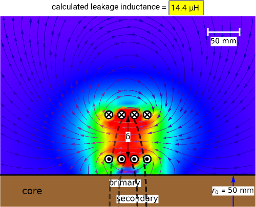
This Demonstration shows how the leakage inductance and the concomitant magnetic field are influenced by the winding configuration. A simple transformer structure with two windings around a cylindrical core is considered. A simplified field calculation technique from [1] is implemented for determining the leakage inductance. For convenience, the primary and secondary windings have the same number of turns, =, with a fixed core radius (=50mm), conductor size (==1.2mm) and winding turn-pitch ().
N
1
N
2
r
0
d
1
d
2
2mm
You can select the winding type: "stacked solenoids", "separated solenoids" or "separated disk windings." You can change the number of turns and the separation distance of the windings. The magnitude of the magnetic field is indicated by the color, and its direction is shown by white arrows.
Although the field is calculated with a relatively fast image method, computation may become slower as the number of turns increases. The primary and secondary currents producing the field are set with the same number of ampere turns, oppositely oriented.