Heat Transfer in a Heat Exchanger
Heat Transfer in a Heat Exchanger


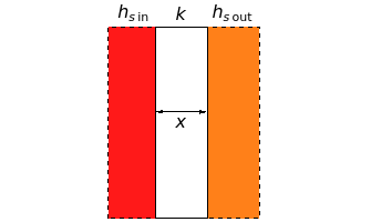
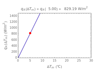
This Demonstration calculates and plots the heat flow, (in watts/), through a heat exchanger's wall of a chosen thickness, (in mm), and thermal conductivity, (in watts/m °C), with chosen surface heat transfer coefficients at either side of the wall, and (in watts/ °C), and logarithmic mean temperature difference, Δ (in °C), between them. Since the heat transfer coefficients can vary over a very large range, the and parameters can be specified as being high or low using a setter bar. The calculations are done using the equation (Δ)=Δ/(1/+x/(1000k)+1/), whose parameters can be modified by moving sliders. The red dot on the plot marks the heat flow per unit area for a Δ chosen by moving the top slider. The top graphic depicts the heat resistances as a schematic diagram (not to scale).
q
A
2
m
x
k
h
sin
h
sout
2
m
T
m
h
sin
h
sout
q
A
T
m
T
m
h
sin
h
sout
T
m