Fields of Magnet Array
Fields of Magnet Array
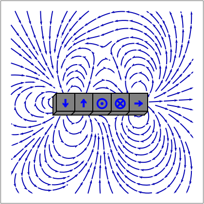
This Demonstration shows the magnetic fields produced by five 1 cm cubic magnets in a linear array. The magnets are held together by a copper axle (not shown), which keeps them from repelling one another but still allows each magnet to be rotated independently. (It is determined in advance which magnets can rotate with their dipoles parallel or normal to the axis.) The magnets have a field strength (more precisely, a magnetic remanence ) that can be selected between 1 and 10 T. Strong fields can be produces by "rare earth" magnets such as neodymium or samarium-cobalt. Since these are extremely brittle and subject to corrosion, they are nickel-plated.
B
B
r
The magnetic field of a small cube is quite well approximated as a point magnetic dipole located at its center, with one of six specified orientations along the coordinate axes, , , , designated by the symbols →, ←, ↑, ↓, ⊙, ⊗, respectively.
±i
±j
±k
The magnetic induction can be expressed in terms of a magnetostatic potential , using . For our array of dipoles, , where is the magnetic moment of the cube.
Φ(r)
B(r)=-∇Φ(r)
μ
0
Φ(r)=·(r-)
5
∑
i=1
m
i
r
i
4π
3
(r-)
r
i
m
i
th
i
You can choose a graphic showing a stream plot for the magnetic lines of force or a density plot giving the magnitude of the magnetic field, with higher field intensity represented by regions of darker blue. The stream plots are scaled proportional to , while the density plots are scaled for maximum variation in color intensity. For visual simplicity, only the and components in the medial plane are included, representing a cross section in the plane.
μ
0
x
y
z=0
One particularly interesting array was created by K. Halbach (ca. 1980) for possible application in particle accelerators. With the sequence of orientations {→, ⊗, ←, ⊙, →}, or, rotated by 90°, {→, ↑, ←, ↓, →}, the magnetic field is large on one side of the array and close to zero on the opposite side.
