Electromagnetic Wave Incident on a Perfect Conductor
Electromagnetic Wave Incident on a Perfect Conductor


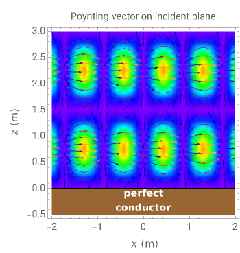
This Demonstration shows an electromagnetic wave incident on a perfect conductor calculates the corresponding Poynting vector. The incident wave is assumed to be linearly polarized in the horizontal or vertical direction (with respect to the electric field). The resulting Poynting vector pattern is shown on the incident - plane. In all cases, the amplitude of the incident electric field is set to =19.4V/m, which corresponds to =0.5 or =1(W) in power density.
x
z
E
peak
S
S
peak
2
m
The Poynting vector is calculated using , where and are the electric and magnetic fields. The fields can be calculated by superposing the fields for the incident and reflected waves. You can show the individual Poynting vectors of the incident wave, the reflected wave, or their superposition.
S=EH
E
H
You can set the frequency in the range 0.1–1.0 GHz and the incident angle at 0–90°. The phase of the sinusoidal cycle can be changed, but this results in time-consuming computations.