Coupler Curve Atlas for the Four-Bar Linkage
Coupler Curve Atlas for the Four-Bar Linkage


In the design of mechanisms, linkages are used to create motions with a specific course of position and speed.
This Demonstration simulates a planar four-bar linkage mechanism and computes the path traced by a point in a fixed position related to its coupler bar.
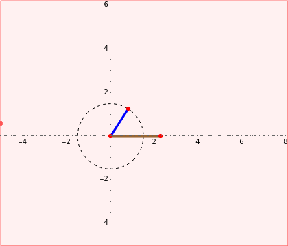
The four bars of the linkage are:
• the ground bar (brown),
• the crank (blue),
• the rocker (orange),
• the coupler bar connecting the crank and rocker (green).
Attached to the coupler bar is a point at a variable offset that you can adjust with the Slider2D control.
(x,y)
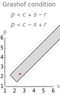
This Demonstration shows a Grashof type linkage [1], that allows at least one link (the crank) to make a complete revolution. Rotate the crank to see how the coupler curve is generated.
A plot under the controls shows the position of the linkage bars with respect to the region where the Grashof condition is met. The Mathematica function RegionNearest is used to keep the bar dimensions within the allowed region.
To highlight the speed evolution of the coupler point, 36 points (one for each of the crank revolution) are located along the generated coupler curve.
10°
Back in 1951, Hrones and Nelson made a comprehensive atlas [2] of about coupler curves, which you can repeat here by varying the parameters in this Demonstration.
10000