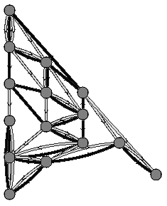
Here's the latest version, with colored ribbon edges, gray circle-nodes with black outlines. Still no doubt some tweaking to be done, like getting rid of the initial node and edges, or having those edges come straight in from no node (could do that with final edges too, have them go straight out instead of omitting them; these two things would be equally easy to do; the information is there, just need to get the directedneighborspicture routine to deal with it). (Not sure how long to make those edges, though; the ones coming out may begin somewhere in the middle of the graph; could make sure they go past the farthest-down node, I guess.) Also you were thinking about putting numbers in the nodes. Let me know what other tweaks you want done. (I also haven't updated the various comments, usage-commands, etc. to reflect most recent changes. Also I didn't
DirectedNeighborsPicture code
DirectedNeighborsPicture code
DirectedNeighborsPicture::usage="DirectedNeighborsPicture[g,init,opts] produces a set of graphic objects which represent the causal network given in g. g is a list of items of the form 0->{{a1,a2,a3},{b1,b2,b3},...} where this means that: there are a2 edges going from node 0 to node a1 and a3-a2 edges going from node a1 to node 0; there are b2 edges going from node 0 to node b1 and b3-b2 edges going from node b1 to node 0; and so on. (This is the form of the output to SMWEvolveListNW.) init is a list containing nodes to put at the top of the network. Options: Reordered->True attempts to order the nodes on each horizontal row to eliminate crossings; Symmetrized->True centers the nodes horizontally; NodeSize is the size of disks drawn at nodes; AspectRatio is the aspect ratio; LightCone->True presents the picture the way I have described it (initial nodes at top, picture is created downwards); if it's false then initial nodes are at left and picture grows to the right; ParallelSeparation is the amount that parallel edges are separated; Dip is the amount that edges between nodes at the same time slice dip downward (if not in Hyperbola mode); Hyperbola->True puts nodes at the same time slice on hyperbolas; Arrows->True gives arrows on the edges; ArrowLength specifies the length of the line segments making up the arrows; ArrowAngle specifies the angle those segments make with the edge; ArrowLocation is a number between 0 and 1 which specifies where the arrow is on the edge (default is .6).";
DirectedNeighborsPictureR[args___]:=DirectedNeighborsPicture[args,Reordered->True]
Options[DirectedNeighborsPicture]={Reordered->False,Symmetrized->True,ParallelSeparation->.1,Dip->.35,Hyperbola->False,NodeSize->0,NodeColor->GrayLevel[.5],AspectRatio->Automatic,LightCone->True,Arrows->False,ArrowLength->.1,ArrowAngle->Pi/6,ArrowLocation->.6,Ribbon->False,RibbonWidth->.03,RibbonPointCount->100,RibbonColorTable->{GrayLevel[.85],GrayLevel[0]}};
QuadraticCurve[{{a_,b_},{c_,d_},{e_,f_}},opts___?OptionQ]:=Module[{coefs,fx,fy,unittangent,unitnormal,arrowvector,loc,arrows,arrowlength,arrowangle,arrowlocation,ar,ribbon,ribbonwidth,ribbonpointcount,ribboncolor,up},{arrows,arrowlength,arrowangle,arrowlocation,ar,ribbon,ribbonwidth,ribbonpointcount,ribboncolor,up}={Arrows,ArrowLength,ArrowAngle,ArrowLocation,AspectRatio,Ribbon,RibbonWidth,RibbonPointCount,RibbonColor,Up}/.{opts}/.Options[QuadraticCurve]; coefs={2#〚3〛-4#〚2〛+2#〚1〛,-#〚3〛+4#〚2〛-3#〚1〛,#〚1〛}&/@{{a,c,e},{b,d,f}}; {fx,fy}=Function[t,{t^2,t,1}.#]&/@coefs; loc=If[up,arrowlocation,1-arrowlocation]; unittangent[t_]:=(#/Sqrt[#.#])&[(2t#〚1〛+#〚2〛)&/@coefs]; unitnormal[t_]:={-#〚2〛,#〚1〛}&@unittangent[t]; arrowvector=-arrowlength(unittangent[loc]); {If[ribbon,Graphics[EdgedPolygon[Join[Table[{fx[t],fy[t]}+ribbonwidth*unitnormal[t],{t,0,1,1/ribbonpointcount}],Table[{fx[t],fy[t]}-ribbonwidth*unitnormal[t],{t,1,0,-1/ribbonpointcount}],{{fx[0],fy[0]}+ribbonwidth*unitnormal[0]}],ribboncolor,GrayStyle],PlotRange->All,AspectRatio->ar],ParametricPlot[{fx[t],fy[t]},{t,0,1},DisplayFunction->Identity,AspectRatio->ar,PlotRange->All,Axes->False]],If[arrows,Graphics[Line[{{fx[loc],fy[loc]},{fx[loc]+{Cos[#],-Sin[#]}.arrowvector,fy[loc]+{Sin[#],Cos[#]}.arrowvector}}]&/@If[up,{arrowangle,-arrowangle},{Pi+arrowangle,Pi-arrowangle}],PlotRange->All,AspectRatio->ar],{}]}]
Options[QuadraticCurve]={Arrows->False,ArrowLength->.1,ArrowAngle->Pi/6,ArrowLocation->.6,AspectRatio->Automatic,Ribbon->False,RibbonWidth->.03,RibbonPointCount->100,RibbonColor->GrayLevel[.85],Up->True};
QuadraticCurve::usage="QuadraticCurve[{{a,b},{c,d},{e,f}},arrows,arrowlength,arrowangle,arrowlocation,ar,up] creates a list of graphics objects for the quadratic curve beginning at {a,b}, passing through {c,d} and ending at {e,f}. If arrow is true, it then draws an arrow pointing towards {e,f} if up is true and towards {a,b} if up is false. The arrow is controlled by the following parameters: arrowlength is the length of the two line segments that make up the arrow (currently this is a coordinate length, not an absolute length); arrowangle is the angle these lines make with the tangent to the curve; arrowlocation is the value of the parameter t where the arrow is to be drawn (t=0 at {a,b}, .5 at {c,d} and 1 at {e,f}). Also, ar is the aspect ratio.";
TransformNW[s_]:=Module[{g,nodes,connectnodes}, g={#〚1,1〛,#〚2,1〛}&/@s; nodes=Union[Flatten[g]]; connectnodes=(Union[g〚#〚1〛,3-#〚2〛〛&/@Position[g,#]])&/@nodes; MapThread[Function[{x,y},x->({#,Count[g,{x,#}],Count[g,{x,#}|{#,x}],Join[Last/@Cases[s,{{x,_},{#,_},_}],Last/@Cases[s,{{#,_},{x,_},_}]]}&)/@y],{nodes,connectnodes}]]
TransformNW::usage="TransformNW[s] deals with directed networks with parallel edges. It takes input from SMWEvolveListNW0 and produces a list of items of the form 0->{{a1,a2,a3},{b1,b2,b3},...} where this means that: there are a2 edges going from node 0 to node a1 and a3-a2 edges going from node a1 to node 0; there are b2 edges going from node 0 to node b1 and b3-b2 edges going from node b1 to node 0; and so on.";
Options[SMWEvolveListNW0]={AddFinalNode->False,IncludeColors->False};
SMWEvolveListNW0[v_,opts___?OptionQ]:= Module{nw={},c=1,state={0,#,StringTake[v〚1,1〛,{#}]}&/@Range[StringLength[v〚1,1〛]],newstate,addfinalnode,includecolors},{addfinalnode,includecolors}={AddFinalNode,IncludeColors}/.{opts}/.Options[SMWEvolveListNW0]; Functiony,IfLength[y〚2〛]>0,newstate=stateRange[1,y〚2,1,1,1〛-1];MapIndexedFunction{z,w},newstate=Join[newstate,{c,#,StringTake[y〚1〛,{#}]}&/@Range@@z〚2〛];nw=Join[nw,If[includecolors,{state〚#,{1,2}〛,{c,#},state〚#,3〛},{state〚#,{1,2}〛,{c,#}}]&/@Range@@z〚1〛]; newstate=Joinnewstate,IfFirst[w]==Length[y〚2〛], stateRange[z〚1,2〛+1,Length[state]], stateRange[z〚1,2〛+1,y〚2,First[w]+1,1,1〛-1]; c++,y2;state=newstate/@Rest[v];If[addfinalnode,nw=Join[nw,MapIndexed[If[includecolors,{#1〚{1,2}〛,{c,First[#2]},#1〚3〛},{#1〚{1,2}〛,{c,First[#2]}}]&,state]]]; nw
SMWEvolveListNWX[rule_,s_,n_]:=TransformNW[SMWEvolveListNW0[SMWEvolveListX[rule,s,n],IncludeColors->True]]
Example
Example
Show[DirectedNeighborsPictureR[SMWEvolveListNWX[{"ABA""BAAB","BBBB""AA"},"ABAAB",25],{0},NodeSize->.15,Hyperbola->True,Arrows->False,Ribbon->True],DisplayFunction->$DisplayFunction];

Show[DirectedNeighborsPictureR[SMWEvolveListNWX[{"ABA""BAAB","BBBB""AA"},"ABAAB",10],{0},NodeSize->.15,Hyperbola->True,Arrows->True,Symmetrized->False,Ribbon->True],DisplayFunction->$DisplayFunction];