To run this code, first run MW-Time-Init.nb, then run everything in the next section. Then try the examples at the end.
DirectedNeighborsPicture code
DirectedNeighborsPicture code
DirectedNeighborsPicture[g_,init_,opts___?OptionQ]:=Module{already=init,next,nextp,xv=0,pbag={},last,lastp,wts,len,pfactor=.1,reord,sym,dbl,pf,ar,cone,rot,arrows,arrowlength,arrowangle,arrowlocation,up},{reord,sym,dbl,ar,cone,arrows,arrowlength,arrowangle,arrowlocation}={Reordered,Symmetrized,DoubleEdges,AspectRatio,LightCone,Arrows,ArrowLength,ArrowAngle,ArrowLocation}/.{opts}/.Options[DirectedNeighborsPicture]; last=init; While(nextp=last/.g;next=Complement[Flatten[If[Length[#]==0,#,First/@#]&/@nextp],already])=!={}, If[reord,wts=(First/@Position[If[Length[#]==0,#,First/@#]&/@nextp,#])&/@next; wts=(Apply[Plus,#]/Length[#])&/@wts;wts=Transpose[{wts,next}];next=Last/@Sort[wts]]; If[sym,pf=(#1-#2/2)&,pf=(#1)&]; If[cone,rot={#〚2〛,-#〚1〛}&,rot=#&]; AppendTo[pbag,Table[If[MemberQ[next,nextp〚i,j,1〛],Table[QuadraticCurve[{a,b}=rot[{xv,pf[i,Length[last]]}];{c,d}=rot[{xv+1,pf[Position[next,nextp〚i,j,1〛]〚1,1〛,Length[next]]}]; {{a,b},{(a+c)*.5+pfactor(k-(nextp〚i,j,3〛+1)/2)(d-b),(b+d)*.5+pfactor(k-(nextp〚i,j,3〛+1)/2)(a-c)},{c,d}},arrows,arrowlength,arrowangle,arrowlocation,ar,If[k>nextp〚i,j,2〛,False,True]],{k,nextp〚i,j,3〛}],{}],{i,Length[last]},{j,Length[nextp〚i〛]}]]; already=Flatten[{already,next}];nextp=next/.g; AppendTopbag,TableIfMemberQ[next,nextp〚i,j,1〛],p=Position[next,nextp〚i,j,1〛]1,1; If[p>i,Table[QuadraticCurve[{a,b}=rot[{xv+1,pf[i,Length[next]]}];{c,d}=rot[{xv+1,pf[p,Length[next]]}];{{a,b},rot[{xv+1.35+pfactor(k-(nextp〚i,j,3〛+1)/2),pf[(i+p)/2,Length[next]]}],{c,d}},arrows,arrowlength,arrowangle,arrowlocation,ar,If[k>nextp〚i,j,2〛,False,True]],{k,nextp〚i,j,3〛}],{}],{},{i,Length[next]},{j,Length[nextp〚i〛]}; xv++;last=next; Flatten[pbag]
DirectedNeighborsPicture::usage="DirectedNeighborsPicture[g,init,opts] produces a set of graphic objects which represent the causal network given in g. g is a list of items of the form 0->{{a1,a2,a3},{b1,b2,b3},...} where this means that: there are a2 edges going from node 0 to node a1 and a3-a2 edges going from node a1 to node 0; there are b2 edges going from node 0 to node b1 and b3-b2 edges going from node b1 to node 0; and so on. (This is the form of the output to SMWEvolveListNW.) init is a list containing nodes to put at the top of the network. Options: Reordered->True attempts to order the nodes on each horizontal row to eliminate crossings; Symmetrized->True centers the nodes horizontally; DoubleEdges and Dotted are not currently implemented (I'm not sure what they were there for); AspectRatio is the aspect ratio; LightCone->True presents the picture the way I have described it (initial nodes at top, picture is created downwards); if it's false then initial nodes are at left and picture grows to the right; Arrows->True gives arrows on the edges; ArrowLength specifies the length of the line segments making up the arrows; ArrowAngle specifies the angle those segments make with the edge; ArrowLocation is a number between 0 and 1 which specifies where the arrow is on the edge (default is .6).";
DirectedNeighborsPictureR[args___]:=DirectedNeighborsPicture[args,Reordered->True]
Options[DirectedNeighborsPicture]={Reordered->False,Symmetrized->False,DoubleEdges->True,Dotted->False,AspectRatio->Automatic,LightCone->False,Arrows->False,ArrowLength->.1,ArrowAngle->Pi/6,ArrowLocation->.6};
QuadraticCurve[{{a_,b_},{c_,d_},{e_,f_}},arrows_,arrowlength_,arrowangle_,arrowlocation_,ar_,up_]:=Module[{coefs,fx,fy,tangentvector,len,loc}, coefs={2#〚3〛-4#〚2〛+2#〚1〛,-#〚3〛+4#〚2〛-3#〚1〛,#〚1〛}&/@{{a,c,e},{b,d,f}}; {fx,fy}=Function[t,{t^2,t,1}.#]&/@coefs; loc=If[up,arrowlocation,1-arrowlocation]; tangentvector=(2loc#〚1〛+#〚2〛)&/@coefs; len=arrowlengthSqrt[tangentvector.tangentvector]; tangentvector=-len(tangentvector); {ParametricPlot[{fx[t],fy[t]},{t,0,1},DisplayFunction->Identity,AspectRatio->ar,PlotRange->All,Axes->False],If[arrows,Graphics[Line[{{fx[loc],fy[loc]},{fx[loc]+{Cos[#],-Sin[#]}.tangentvector,fy[loc]+{Sin[#],Cos[#]}.tangentvector}}]&/@If[up,{arrowangle,-arrowangle},{Pi+arrowangle,Pi-arrowangle}],PlotRange->All,AspectRatio->ar],{}]}]
QuadraticCurve::usage="QuadraticCurve[{{a,b},{c,d},{e,f}},arrows,arrowlength,arrowangle,arrowlocation,ar,up] creates a list of graphics objects for the quadratic curve beginning at {a,b}, passing through {c,d} and ending at {e,f}. If arrow is true, it then draws an arrow pointing towards {e,f} if up is true and towards {a,b} if up is false. The arrow is controlled by the following parameters: arrowlength is the length of the two line segments that make up the arrow (currently this is a coordinate length, not an absolute length); arrowangle is the angle these lines make with the tangent to the curve; arrowlocation is the value of the parameter t where the arrow is to be drawn (t=0 at {a,b}, .5 at {c,d} and 1 at {e,f}). Also, ar is the aspect ratio.";
TransformNW[s_]:=Module[{g,nodes,connectnodes}, g=(First/@#)&/@s; nodes=Union[Flatten[g]]; connectnodes=(Union[g〚#〚1〛,3-#〚2〛〛&/@Position[g,#]])&/@nodes; MapThread[Function[{x,y},x->({#,Count[g,{x,#}],Count[g,{x,#}|{#,x}]}&)/@y],{nodes,connectnodes}]]
TransformNW::usage="TransformNW[s] deals with directed networks with parallel edges. It takes input from SMWEvolveListNW0 and produces a list of items of the form 0->{{a1,a2,a3},{b1,b2,b3},...} where this means that: there are a2 edges going from node 0 to node a1 and a3-a2 edges going from node a1 to node 0; there are b2 edges going from node 0 to node b1 and b3-b2 edges going from node b1 to node 0; and so on.";
Examples
Examples
TransformNW[SMWEvolveListNW0[SMWEvolveListX[{"ABA""BAAB","BBBB""AA"},"ABAAB",25]]]
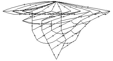
Show[DirectedNeighborsPictureR[SMWEvolveListNW[{"ABA""BAAB","BBBB""AA"},"ABAAB",25],{0},Symmetrized->True,LightCone->True,Arrows->True],DisplayFunction->$DisplayFunction];
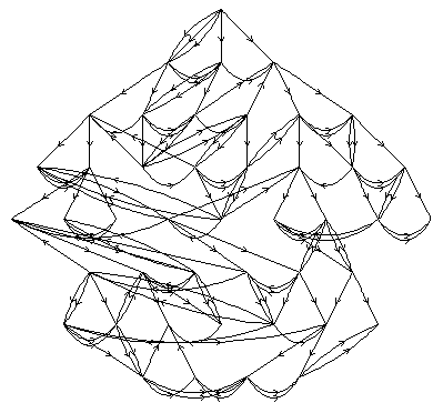
Show[DirectedNeighborsPictureR[SMWEvolveListNW[{"BA"->"AB"},RandomString[20],25],{0},Symmetrized->True,LightCone->True,Arrows->True],DisplayFunction->$DisplayFunction];