2022 Solution 09
2022 Solution 09
Isaac P Abraham
2022 September 30
2022 September 30
The figure will render in about 10 seconds.
Out[]=
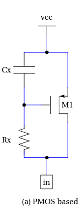
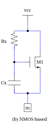
The above diagrams are transcribed from Razavi, B., “The Active Inductor” (A Circuit for all Seasons), IEEE Solid-State Circuits Magazine, Spring 2020. Panel (a) is Figure 11 and Panel (b) is Figure 5. Ignoring any parasitic manifestations, what is the profile (orientation) of the output impedance vs. frequency, for circuit (a) and (b)? Answers should be of the form (i) (a) increasing, (b) decreasing or (ii) (a) and (b) flat or (iii) (a) and (b) both increasing etc.
ro
M1
■ Reply no later than a couple of days before the end of the month to isaac.abraham@intel.com, Subject “Analog Beat 2022 Problem #”. Last reply of multiple replies will be considered. Earlier replies help with tie-breaks at the end.
Assume that both circuits are biased correctly, as they should be. At higher frequencies, the MOSFET gates see less of the signal - increasing the drain~source resistance both circuits.