2019 Solution 03
2019 Solution 03
Consider the non-inverting amplifier configuration above with an ideal opamp having a finite gain A.
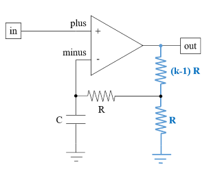
What is the circuit gain as ω ∞.
(a) A
(b) k
(c) 1/k
(d) R*Xc
(a) A
(b) k
(c) 1/k
(d) R*Xc
Let the gain of the amplifier be A. We can write the following equations by inspection.
(vin-vminus)A=vout
(
1
)voutβ=vminus
Xc
R+Xc
(
2
)β=
1
k
(
3
)We can back substitute from (3) (2) (1) to generate a compact equation. Substitute for β from (3) into (2).
vout=vminus
1
k
Xc
R+Xc
(
4
)Now substitute this information for vminus back into (1).
vin-voutA=vout
1
k
Xc
R+Xc
(
5
)Transpose terms.
Avin=vout1+A
1
k
Xc
R+Xc
(
6
)Generate the transfer function.
vout
vin
A
1+A
1
k
Xc
R+Xc
(
7
)Expand the Xc since we’re only interested in magnitude and rewrite (7).
1
ωC
vout
vin
A
1+A
1
k
1
ωR+1
(
8
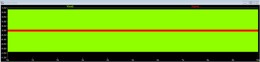
)Evaluate () as ω ∞; which is easily done.
0
vout
vin
(
9
)SPICE
SPICE
A SPICE simulation of the circuit was setup with the following parameters.
Circuit__: R = 10kΩ, C = 1μF and k = 1.58.
Opamp_: A = 20, GBW = 10MHz.
Stimulus: 0.05 sin(2 π 1000 t).
Note that the input frequency of 1 kHz is much larger than the R-C time constant of the circuit of 10 ms (100 Hz); satisfying the assumption that ω ∞ (compared to the time constants in the network).