2019 Solution 02
2019 Solution 02
Consider the following circuit topology with two cascaded LPFs.
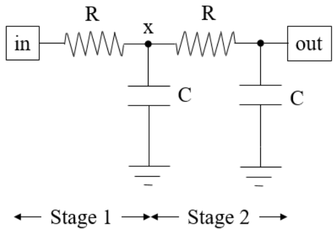
Assume that the input connects to a source (not shown) with 0 Ω source resistance while the output is open.
Choose the correct statement about the circuit. In the following choices, Znode_name stands for the impedance at the named net; for input frequencies well below the corner frequency.
(a) Zx < Zout
(b) Zx = Zout
(c) Zx > Zout
(d) Zx → Zout. The symbol → means “tends to” or “approaches”; but never exactly equal.
Visual inspection shows that the impedances at node x and out are,
Zx = (R//Xc) // (R+Xc) and Zout = Xc//(R+R//Xc)
Let R//Xc = P where P < [Xc, R] as happens during paralleling elements.
Zx = P // (R + Xc) ~ P and Zout = Xc//(R + P) ~ Xc > P; thus (a) Zx < Zout.
For a SPICE setup, ensure that the stimulus is applied into the node being studied. The stimulus applied into net x has greater attenuation (due to lower impedance) than into net out.