World’s largest amateur electromagnet
World’s largest amateur electromagnet
In this post, I’ll walk you through how I built what I believe to be the world’s largest amateur electromagnet with the Wolfram Language. I needed this large, strong electromagnet to continue studying highly magnetized (collisionless) plasmas. After examining the requirements of the plasma process, I determined that a highly homogenous magnetic field region with a strength of 160mT, diameter of about an inch and a length of about 2 feet would be sufficient. As you can imagine, an electromagnet requires a lot of wire, and wire is not cheap.
In fact, the prices of copper have really climbed in the last few months. So the difficulty is not really how to build such a magnet, but how to achieve the needed parameters while being cost-effective. Fortunately, we have the Wolfram Language, and we can use real wire prices and component prices and let the Wolfram Language find the best option, including the power supply.
In this post, we’ll briefly consider the theory behind electromagnets, as well as the practicalities of building one. Then we will let the Wolfram Language consider many thousands of different designs and tell us the best option. Finally, I’ll share some photos of the built system as well as some helpful tips for anyone thinking of building a large electromagnet.
The Theory of Electromagnets
The Theory of Electromagnets
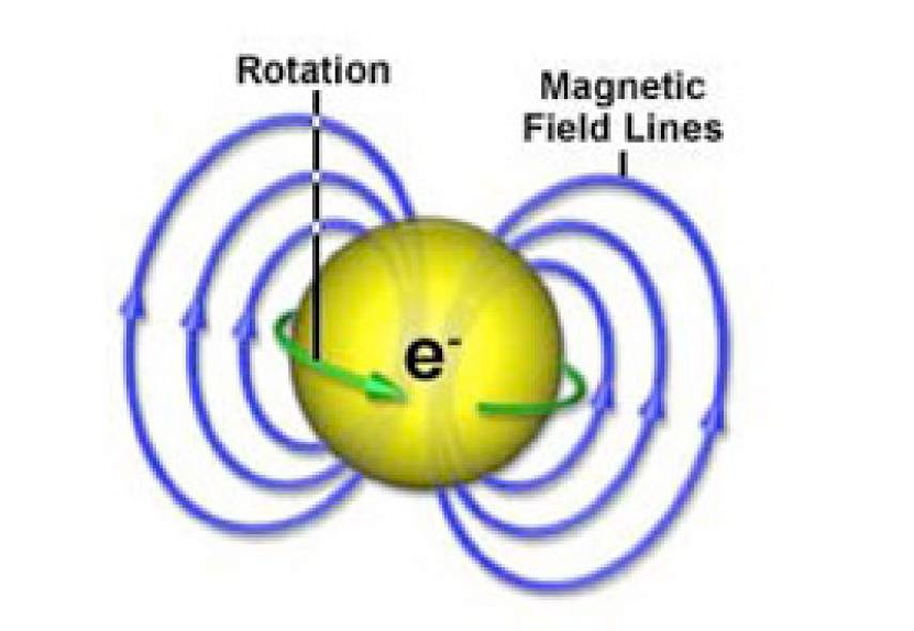
This is a very deep and complex topic, but we will stick to the bare minimum theory required to design an electromagnet. If you aren’t interested, feel free to scroll down for photos of big electromagnets. When an electron moves, it creates a magnetic field that rotates around that electron:
If you have a lot of electrons moving in the same direction, as in a current-carrying wire, you amplify that effect:
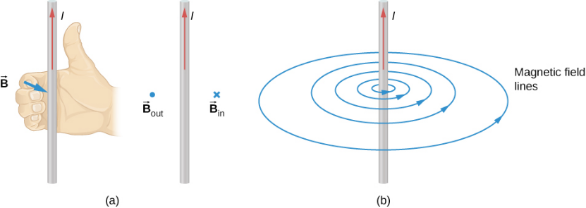
If you then loop that wire around, you can direct the magnetic field lines in an axial direction:
And there’s basically your electromagnet. We’re not done yet - how do you create fields that are really uniform? In the next section we will consider several different coil configurations that improve the homogeneity of an electromagnet.
Some resources to dive deeper:
Great place for beginners: http://hyperphysics.phy-astr.gsu.edu/hbase/magnetic/magfie.html#c1
For advanced learning: https://press.princeton.edu/books/hardcover/9780691159027/modern-classical-physics
Great place for beginners: http://hyperphysics.phy-astr.gsu.edu/hbase/magnetic/magfie.html#c1
For advanced learning: https://press.princeton.edu/books/hardcover/9780691159027/modern-classical-physics
Multi-Coil Homogenous Electromagnets
Multi-Coil Homogenous Electromagnets
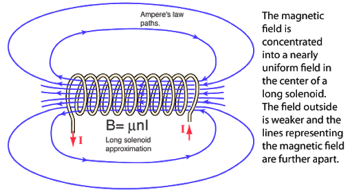
If a “multi-coil like above (commonly called a solenoid) is infinitely long, then the field within it is uniform. When a solenoid has a finite length, the field is stronger in the middle then at the end:
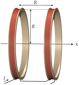
One of the earliest solutions was to use two current carrying loops that were spaced a special distance apart. This was called a Helmholz coil (or Helmholz pair) and you can try out various configurations with this Manipulate:
Out[]=


What if we need higher levels of homogeneity? There is an improved version of the Helmholz coil, called a Maxwell coil, that uses 3 rather than 2 loops, and those loops are placed on the surface of a virtual sphere:
Extending this, if you were to add more and more loops on the surface of a sphere, you would eventually get a perfectly homogenous field. The issue is that field has a very large and isotropic volume, and many applications including mine require a longer field with a small radius.
The standard practice here is to use a solenoid with certain parts spaced out. This is optimized numerically using a program like Mathematica. After playing around with that kind of optimization I realized that it greatly increased the complexity of construction: I’d have to very precisely space wraps of wire, and doing do did not lead to a large improvement in performance. So I decided to use a traditional solenoid, and if I used enough turns and the working volume was sufficiently in the interior, there should be a very homogenous field.
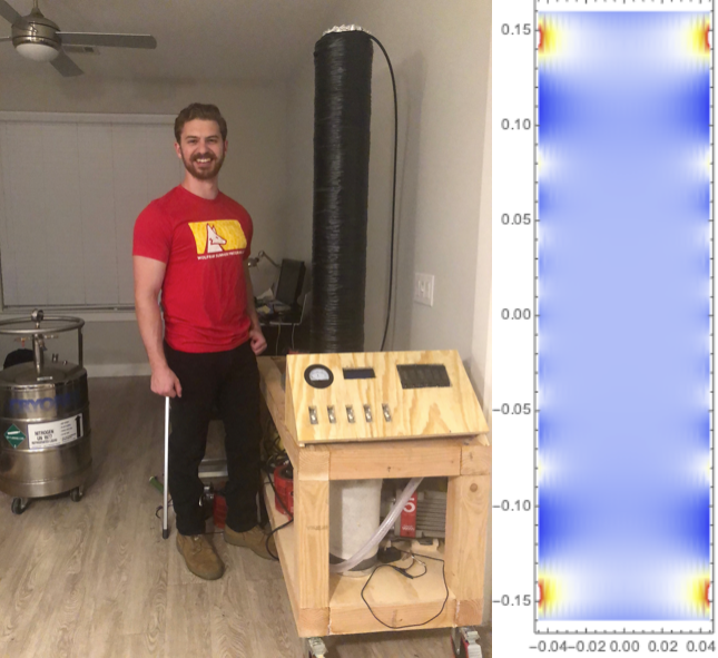
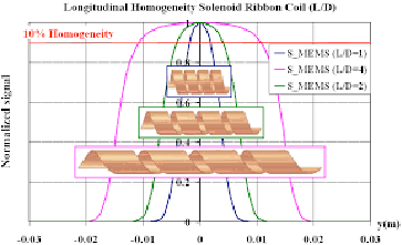
I spent a lot of time looking at optimized geometries for producing a homogenous field before realizing the “juice wasn’t worth the squeeze”. At least it resulted in a lot of nice-looking plots of the magnet homogeneity:
I may write a later post about optimizing electromagnet geometries with the Wolfram Language. If anyone is interested in the code (and optimization methods, of which there are plenty) let me know in the comments. Here’s a graphic (code way too long and slow) looking at the homogeneity in the central region of two very optimized coils (full coil on left, then a zoomed in section for the region inside the box, two coils being compared):
Coil Cost Optimization, Part 1
Coil Cost Optimization, Part 1
Here’s a Manipulate I built for optimizing a Maxwell coil; it gives a user a good feel for the performance tradeoffs:
After playing around with it, you can see one of the big issues is power dissipation. Highly resistive electromagnets will necessarily dissipate a lot of power, whereas using more conductor volume will decrease power dissipation and consumption but greatly increase the cost.
If the major driver of cost is the conductor volume, what about using a different conductor? My first thought was making the electromagnet out of hollow copper pipe and running liquid nitrogen through the coil. When at liquid nitrogen temperatures, copper is about 10x more conductive, and liquid nitrogen is orders of magnitude cheaper than copper...
I happen to have a 50 liter liquid nitrogen dewar, but ultimately I decided against this route; it would be much more convenient to have no consumables. Just flip a switch on, and the electromagnet goes on. The next idea: is copper the most cost-effective conductor of electricity?
I happen to have a 50 liter liquid nitrogen dewar, but ultimately I decided against this route; it would be much more convenient to have no consumables. Just flip a switch on, and the electromagnet goes on. The next idea: is copper the most cost-effective conductor of electricity?
Coil Conductor Optimization
Coil Conductor Optimization
What about using aluminum as the conductor?
Okay, so aluminum has 60% of copper’s electrical conductivity, what about its price? Looking at Home Depot’s website for 0AWG copper vs. aluminum wire, you’ll find that the copper wire is $2.34/ft, and the aluminum wire is $0.75/ft (as of the time of this writing).
So aluminum is the clear winner; it’s almost half as conductive but is three times cheaper. A strange quirk of wire manufacture is that some gauges are cheaper. Since the driving factor for cost is conductor volume, what gauge aluminum wire is cheapest per unit conductor volume?
So 2AWG aluminum wire is the cheapest, by a considerable amount (at this time). So that’s what we’ll use for the electromagnet. Here’s the delivered #2AWG aluminum wire:
Modelling Electromagnets in the Wolfram Language
Modelling Electromagnets in the Wolfram Language
First, let’s define the actual equation for a magnetic field in three dimensions:
The equations come from “Some Useful Information for the Design of Air-Core Solenoids”, by D. Bruce Montgomery, and here’s an illustration of what the variables refer to:
Here’s a function version:
Which we can immediately start using to visualize a magnetic field generated by a current loop, for instance:
Of course, since a solenoid is just a lot of current-carrying loops, we can use this function (with some kind of iteration) to model solenoids:
These functions, in combination with data about the resistivity and cost of wire, as well as general equations like Ohm’s law, will suffice for coming up with an optimal electromagnet configuration.
Coil Cost Optimization, Part 2
Coil Cost Optimization, Part 2
So, what’s the most cost-effective design for the electromagnet? Let’s define a function that will output a lot of relevant parameters:
The tube I am wrapping the electromagnet around (actually a vacuum chamber) is 50 inches long, and due to the width (with insulation) of #2AWG wire, can be wrapped about 130 times end to end per layer. After playing around with 1-5 layer designs, three wraps give the best result:
Power Supply for Driving the Electromagnet
Power Supply for Driving the Electromagnet
Continuous power implies using power from an outlet, i.e. 120V, 20A (max) alternating current. Like many power supplies, this voltage will be transformed (stepped down in this case) and then rectified (made to be direct current). Using large step down transformers, it isn’t hard to generate pretty large currents (100A+) at low voltages (>20V), and the main issue lies in rectification and current smoothing. Typically in rectification one might use a ‘diode bridge’ composed of two pairs of opposing diodes:
The issue is that every diode has a ‘voltage drop’ which is intrinsic to its operation as a semiconductor. There’s no way around it. The only thing to do is to find the lowest voltage drop diode that can handle the necessary current and voltage. After a quick search/filter in Digikey, the top results (by far) was the 242NQ030PBF. Their datasheet says they have a “low voltage drop” and are rated to rectify 240A in a full bridge rectifier. Here’s what they look like in person (before they have to be epoxied with very expensive silver-filled epoxy to a massive heat sink):
Transformers are also needed. I got lucky and found 2 massive (50lbs apiece!) transformers that had been wired to transform 12V to 120V, which is exactly the inverse of what I needed. They were filthy (see below) but work great. Theoretically I only needed one, but I used two to reduce the current required to any single transformer and any single outlet.
Building the Electromagnet, and Lessons Learned
Building the Electromagnet, and Lessons Learned
Building an electromagnet is really just the task of wrapping it and getting it to stay wrapped - and therein lies the problem. Long lengths of wire come on a spool of large diameter, and hence the wire does not tend to stay wrapped but to unravel itself. Adhesives of some sort could be used to attach the wire both to itself and to the tube it’s being wrapped on, but their are two major issues conspiring against successful adherence. Firstly, the wire is of circular cross section and so has a very small contact surface area both with adjacent wire and with a mounting tube. Secondly, the wire I got has cross-linked polyethylene insulation, and polyethylene has one of the lowest known surface activation energies and thus almost no adhesives will work! I myself tried many adhesives and found the only workable thing to be a high-temperature hot melt adhesive which I suspect is itself polyethylene. So be very careful in deciding what wire to use and pay attention to the insulation material. I found it very helpful to construct a jig with which to wind the electromagnet. When totally wound, it weighs over 125 pounds, so using a jig to support it as you wind it will save you a lot of time and effort.
If you’re interested in exploring Wolfram technologies and their applications to science, technology, education and more you may be interested in Wolfram Summer School, an incredible research and learning experience that I am proud to help lead this year. I highly encourage you to learn more about it and apply! https://education.wolfram.com/summer-school/