In this short computational essay, I quickly reviewed the concept of quantum error correction, in particular for a bit-flip error case. I first represented how one can detect and correct the error using logical qubits. Then the corresponding quantum implementation is discussed using the Wolfram Quantum Computation Framework. Note we have considered the case where a bit-flip error can happen for only one single qubit, and neglected cases with two or more simultaneous errors. Finally, I commented on quantum channels, as one way of modeling errors.
Parity of a bit string
Parity of a bit string
By parity of a bit string, we mean if the bit string has an even or odd number of 1’s. It can be determined by XOR. For example:
Even parity corresponds to 0:
In[]:=
BitXor@@{0,0,1,1}
Out[]=
0
Odd parity corresponds to 1:
In[]:=
BitXor@@{1,0,1,1}
Out[]=
1
Let us use a 3-bit numbers 000 and 111, as the logical bits 0 and 1, respectively. Independently, let’s calculate the parity (XOR) of two leftmost and two rightmost bits for all 3-bits code words.
In[]:=
<|"{,,}"->#,"⊕"->BitXor@@#[[;;2]],"⊕"->BitXor@@#[[2;;]]|>&/@Tuples[{0,1},3]//Dataset
b
1
b
2
b
3
b
1
b
2
b
2
b
3
Out[]=
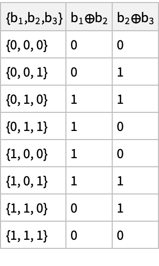
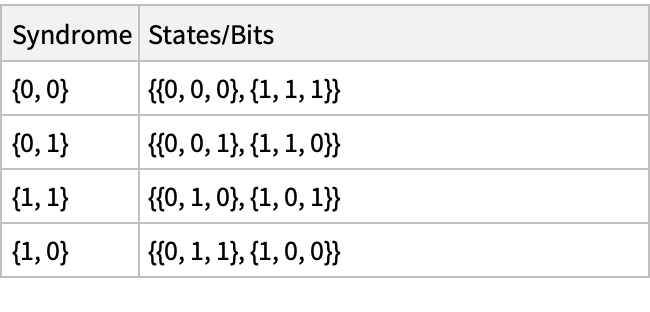
Grouping the 3-bits code words using the parity results (as explained above), one gets:
In[]:=
GroupBy[{#,BitXor@@@Partition[#,2,1]}&/@Tuples[{0,1},3],Last->First]
Out[]=
{0,0}{{0,0,0},{1,1,1}},{0,1}{{0,0,1},{1,1,0}},{1,1}{{0,1,0},{1,0,1}},{1,0}{{0,1,1},{1,0,0}}
In[]:=
KeyValueMap[<|"Syndrome"->#1,"States/Bits"->ToString@#2|>&][%]//Dataset
Out[]=
We will consider cases that only one single bit-flip error can happen.
Comparing with the logical bits, the corresponding parity pairs (i.e. calling them the “syndrome”) for nothing (no error) will be {0,0}. A bit-flip on the 3rd bit corresponds to the syndrome {0,1}; a bit-flip on 2nd bit corresponds to the syndrome {1,1}; and finally {1,0} is the syndrome for one bit-flip on the 1st bit.
Quantum version of parity measurements
Quantum version of parity measurements
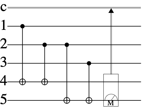
Note if we measure parities, without knowing the actual codeword, we can uniquely determine what single bit-flip error happened.
In[]:=
syndromeQC=QuantumCircuitOperator[{QuantumOperator["CNOT",{1,4}],QuantumOperator["CNOT",{2,4}],QuantumOperator["CNOT",{2,5}],QuantumOperator["CNOT",{3,5}],QuantumMeasurementOperator[{4,5}]}];syndromeQC["Diagram"]
Out[]=
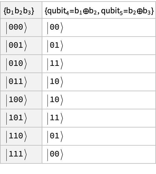
Create all combination of 0 and 1 for qubit 1-3, and set qubits-4,5 as 0, only:
In[]:=
states=QuantumState[StringJoin[#]<>"00"]&/@Tuples[{"0","1"},3];
Return the error detection result:
In[]:=
<|{""}->{"=⊕, =⊕"},AssociationThread[QuantumState[StringJoin[#]]["Formula"]&/@Tuples[{"0","1"},3],syndromeQC[#]["TopProbabilities"->1][[1,1]]&/@states]|>//Dataset
b
1
b
2
b
3
qubit
4
b
1
b
2
qubit
5
b
2
b
3
Out[]=
Correction scheme
Correction scheme
Assuming only a single bit-flip, design a circuit to correct it:
In[]:=
correction=QuantumCircuitOperator[{QuantumOperator[{"Controlled","X",{5},{4}},{3}],QuantumOperator[{"Controlled","X",{4,5}},{2}],QuantumOperator[{"Controlled","X",{4},{5}},{1}]}];correction["Diagram"]
Out[]=
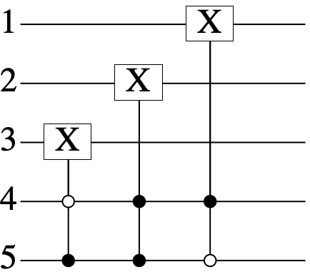
Note that the 2nd operation for error detection and correction is the same as a Toffoli gate
In[]:=
QuantumOperator[{"Controlled","X",{4,5}},{2}]==QuantumOperator["Toffoli",{4,5,2}]
Out[]=
True
Preparing the information qubit (qubit-1) in a superposition state
In[]:=
ψ0=QuantumState[{α,β}]
Out[]=
QuantumState


Circuit for preparing the initial superposition as α |000〉+β |111〉:
In[]:=
prep=QuantumCircuitOperator[{QuantumOperator["CNOT"],QuantumOperator["CNOT",{1,3}]}];prep["Diagram"]
Out[]=
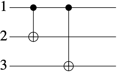
Setting qubit 1-3 in the state α |000〉+β |111〉, and then qubits 4 and 5 in 0, only:
In[]:=
state=prep[QuantumTensorProduct[ψ0,QuantumState["00"]]];state["Formula"]
Out[]=
α|000〉+β|111〉
Generate a noise channel, where different operators can act on qubits 1-3:
In[]:=
ℰr[q1_,q2_,q3_]:=Fold[#2[#1]&,{QuantumOperator[q1],QuantumOperator[q2,{2}],QuantumOperator[q3,{3}]}]
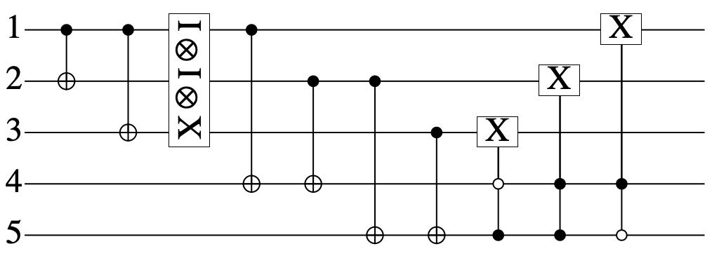
Set the error as bit-flip on the qubit-3:
In[]:=
qc=QuantumCircuitOperator[Join[prep[[1]],{ℰr["X","Identity","Identity"]},Most@syndromeQC[[1]],correction[[1]]]];qc["Diagram"]
Out[]=
Apply the circuit on the initial state:
Compare the final state with the initial one, after tracing out qubits 4 and 5:
Set the error channel as two bit-flip on qubit 1 and 3 (we will show, the circuit cannot correct this error):
Apply circuit on the state:
Compare the reduced state of qubits 1-3 with the initial state:
As expected the final state is different. Note the above circuit can correct only one bit-flip error.
One can assume that due to a noisy channel, with a probability of p, a flip error (Pauli-X) can happen on any qubit. This channel can be constructed as follows:
Note whenever you evaluate above code, you get a different noise operator. Also, one-qubit error/flip, two and also three are possible (of course, with lesser probabilities).
Quantum channel
Quantum channel
Define quantum channel
Check that operators are trace preserving (note it is a property of channel, in the summary box above)
Define a random 2D pure state
The effect of channel on that
Visualizing quantum channels in Bloch sphere
Visualizing quantum channels in Bloch sphere
Let us explore the effect of different channels on the Bloch sphere. We shall start by defining a normalized pure state
Visualize it
Effect of different channels on the Bloch sphere:
Paclet installation
Paclet installation