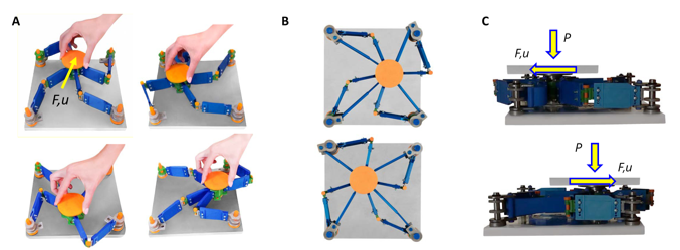
Physical models and experimental validation of the SSI. (A) Motion animation of a demonstrative version of prototype #1 equipped with fully 3D-printed unit cell parts, which can be moved by hand. (B) Demonstrative version of prototype #2 equipped with telescopic tendons (see Movie S3 for a motion video-clip). (C) Prototype #2 with stretchable tendons and metallic posts under testing.
Motion animation of a demonstrative prototype with fully 3D-printed unit cell parts and telescopic tendons.
Featured video of the deformation of the tendons of the biomimetic sliding-stretching isolator under testing.
A device inspired by human arms and legs could help to reduce how much a building shakes during an earthquake. Seismic isolators are placed between a structure and its foundations to protect against shaking ground. They are already widely used, but are generally expensive and difficult to install.
Fernando Fraternali at the University of Salerno in Italy and his colleagues took a different approach. Their prototype consists of four ‘limbs’ with joints that connect a central post to the four corners of a plate. The post rests on a slippery circular disk called a slider and is connected to the ends of the limbs by stretchable ‘tendons’ made of thermoplastic polyurethane.
When the researchers moved the post from its central position, friction and the restorative nature of the tendons dampened its motion. The device, which can be built using 3D-printed components and other common tools and metallic parts, could make it easier and cheaper to protect structures from earthquakes. The tendons’ size and composition can be changed, which could make them more tuneable than the rubber bearings used in many conventional seismic isolators, the scientists say.
doi: https://doi.org/10.1038/d41586-021-03506-2
Analytic form of the kinematics for arbitrary rest configuration
Analytic form of the kinematics for arbitrary rest configuration
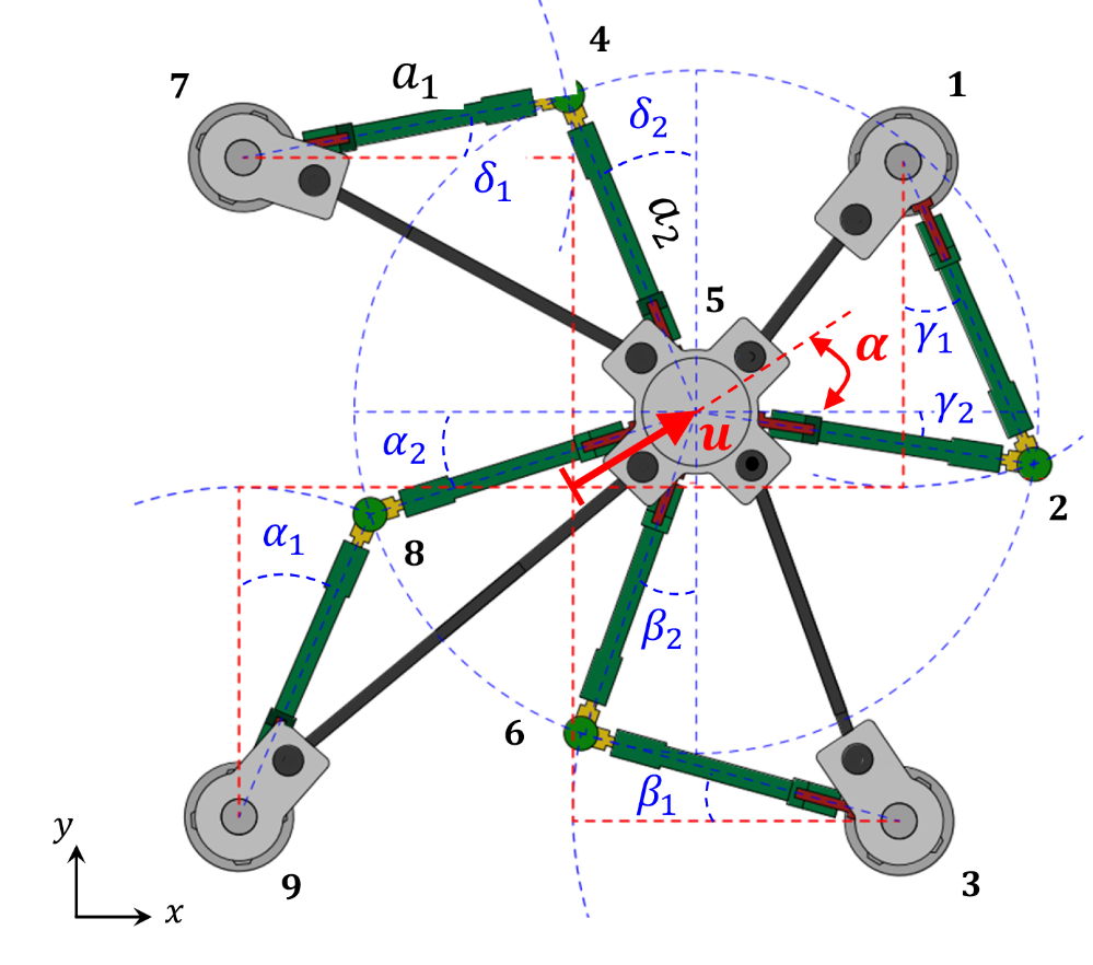
Top view of the deformed configuration of the SSI unit cell.
Notation
n[i] =nundef[i]=nbeta[i]=nundefbeta[i] denote the undeformed node coordinates
ndef[i] = ndefbeta[i] denote the deformed node coordinates
v denotes the lateral displacement of the SSI (denoted u in the main Article and the Methods section)
n[i] =nundef[i]=nbeta[i]=nundefbeta[i] denote the undeformed node coordinates
ndef[i] = ndefbeta[i] denote the deformed node coordinates
v denotes the lateral displacement of the SSI (denoted u in the main Article and the Methods section)
General data
General data
In[]:=
Clear[adata,vdata]adata={};vdata={vactv,anglealpha(alphav)};cdata={C[1]0,C[2]0};kloadata={Cos[anglealpha],Sin[anglealpha],0}/.vdata
Out[]=
{Cos[alphav],Sin[alphav],0}
Undeformed node coordinates
Undeformed node coordinates
In[]:=
nnodes=9;
In[]:=
n[1]={a2+a1*Sin[beta],a1*Cos[beta],0}/.adata;n[2]={a2,0,0}/.adata;n[3]={a1*Cos[beta],-a2-a1*Sin[beta],0}/.adata;n[4]={0,a2,0}/.adata;n[5]={0,0,0}/.adata;n[6]={0,-a2,0}/.adata;n[7]={-a1*Cos[beta],a2+a1*Sin[beta],0}/.adata;n[8]={-a2,0,0}/.adata;n[9]={-a2-a1*Sin[beta],-a1*Cos[beta],0}/.adata;
In[]:=
Do[nundef[i]=n[i],{i,1,nnodes}];
In[]:=
a89=a1/.adata;a58=a2/.adata;a63=a1/.adata;a56=a2/.adata;a12=a1/.adata;a52=a2/.adata;a54=a2/.adata;a74=a1/.adata;
In[]:=
Do[nbeta[i]=n[i];nundefbeta[i]=nbeta[i],{i,1,nnodes}];
Solve the analytic form of the unit-cell kinematics (see Methods) for a1, a2 angles
Solve the analytic form of the unit-cell kinematics (see Methods) for a1, a2 angles
(a1=alpha1, a2=alpha2 with the notation of Fig. S2 A)
In[]:=
n8xdefa=(n[9][[1]]+a89*Sin[anglea1])/.vdata;n8xdefb=((n[5][[1]]+vact*Cos[anglealpha])-a58*Cos[anglea2])/.vdata;n8ydefa=(n[9][[2]]+a89*Cos[anglea1])/.vdata;n8ydefb=((n[5][[2]]+vact*Sin[anglealpha])-a58*Sin[anglea2])/.vdata;eq8x=n8xdefan8xdefb;eq8y=n8ydefan8ydefb;angleasol=Solve[{eq8x,eq8y},{anglea1,anglea2}]/.cdata//Simplify;isol=1;angleasol[[isol]]n8xdefa/.angleasol;n8xdefb/.angleasol;n8ydefa/.angleasol;n8ydefb/.angleasol;n[8];
Out[]=
Solve the analytic form of the unit-cell kinematics for b1, b2 angles
Solve the analytic form of the unit-cell kinematics for b1, b2 angles
(b1=beta1, b2=beta2 with the notation of Fig. S2, A)
In[]:=
n6xdefa=(n[3][[1]]-a63*Cos[angleb1])/.vdata;n6xdefb=((n[5][[1]]+vact*Cos[anglealpha])-a56*Sin[angleb2])/.vdata;n6ydefa=(n[3][[2]]+a63*Sin[angleb1])/.vdata;n6ydefb=((n[5][[2]]+vact*Sin[anglealpha])-a56*Cos[angleb2])/.vdata;eq6x=n6xdefan6xdefb;eq6y=n6ydefan6ydefb;anglebsol=Solve[{eq6x,eq6y},{angleb1,angleb2}]/.cdata//Simplify;isol=1;anglebsol[[isol]]n6xdefa/.anglebsol;n6xdefb/.anglebsol;n6ydefa/.anglebsol;n6ydefb/.anglebsol;n[6];
Out[]=
Solve the analytic form of the unit-cell kinematics for c1, c2 angles
Solve the analytic form of the unit-cell kinematics for c1, c2 angles
(c1=gamma1, c2=gamma2 with the notation of Fig. S2, A)
In[]:=
n2xdefa=(n[1][[1]]+a12*Sin[anglec1])/.vdata;n2xdefb=((n[5][[1]]+vact*Cos[anglealpha])+a52*Cos[anglec2])/.vdata;n2ydefa=(n[1][[2]]-a12*Cos[anglec1])/.vdata;n2ydefb=((n[5][[2]]+vact*Sin[anglealpha])-a52*Sin[anglec2])/.vdata;eq2x=n2xdefan2xdefb;eq2y=n2ydefan2ydefb;anglecsol=Solve[{eq2x,eq2y},{anglec1,anglec2}]/.cdata//Simplify;isol=1;anglecsol[[isol]]n2xdefa/.anglecsol;n2xdefb/.anglecsol;n2ydefa/.anglecsol;n2ydefb/.anglecsol;n[2];
Solve the analytic form of the unit-cell kinematics for d1, d2 angles
Solve the analytic form of the unit-cell kinematics for d1, d2 angles
(d1=delta1, d2=delta2 with the notation of Fig. S2, A)
Node coordinates in the deformed configuration
Node coordinates in the deformed configuration
Analytic computation of the locking geometry for arbitrary rest configuration
Analytic computation of the locking geometry for arbitrary rest configuration
(A) Kinematics of the unit cell. (B) Locking displacements versus loading angle alpha and rest angle beta. (C) Deformed configuration of a two-layer system.
First locking condition for the alignment of the limb members 5-8 and 8-9 (Fig. S2, A)
First locking condition for the alignment of the limb members 5-8 and 8-9 (Fig. S2, A)
Second locking condition for the alignment of the limb members 5-6 and 6-3 (Fig. S2, A)
Second locking condition for the alignment of the limb members 5-6 and 6-3 (Fig. S2, A)
Third locking condition for the alignment of the limb members 5-2 and 2-1 (Fig. S2, A)
Third locking condition for the alignment of the limb members 5-2 and 2-1 (Fig. S2, A)
Fourth locking condition for the alignment of the limb members 5-4 and 4-7 (Fig. S2, A)
Fourth locking condition for the alignment of the limb members 5-4 and 4-7 (Fig. S2, A)
Find vmax vs alpha law for beta = 0 deg
Find vmax vs alpha law for beta = 0 deg
(vmax=u_{lock} with the notation of the main text)
Analytic expression of vbarlock (vbarlock={\bar u}_{lock} with the notation of the main text)
Analytic expression of vbarlock (vbarlock={\bar u}_{lock} with the notation of the main text)
Plot of vbarlock for varying alpha
Plot of vbarlock for varying alpha
Engineering axial strains of the tendons
Engineering axial strains of the tendons
Plot the locking strains vs loading angle alpha
Plot the locking strains vs loading angle alpha
Find vmax vs alpha law for a1=a2=a, beta = 10 deg
Find vmax vs alpha law for a1=a2=a, beta = 10 deg
Find vmax vs alpha law for a1=a2=a, beta = 5 deg
Find vmax vs alpha law for a1=a2=a, beta = 5 deg
Find vmax vs alpha law for a1=a2=a, beta = -5 deg
Find vmax vs alpha law for a1=a2=a, beta = -5 deg
Find vmax vs alpha law for a1=a2=a, beta = -10deg
Find vmax vs alpha law for a1=a2=a, beta = -10deg
Global vlock vs. alpha chart
Global vlock vs. alpha chart