1. Problem Statement
1. Problem Statement
The aim of the project is to create a minimal circuit using R, L, C, and M (resistors, capacitors, inductors and transformers) elements that generates a specific output signal.
Circuit minimization significantly enhances its characteristics. A circuit with fewer components is more cost-effective, as it increases reliability, simplifies maintenance and troubleshooting, and reduces the likelihood of component failure, while also requiring less space for storage. The Brune method of circuit synthesis will be employed to achieve circuit minimization.
2. Laplace Transform
2. Laplace Transform
Equations describing current and voltage, denoted as and , are typically differential in nature. The application of the Laplace transform converts these equations into algebraic expressions, facilitating easier manipulation and analysis.
V(t)
I(t)
The Laplace Transform is a mathematical technique that converts a time-domain function, typically represented as , into a frequency-domain representation, denoted as , where is a complex frequency variable. This transformation simplifies the analysis of systems characterized by differential equations, making it an essential tool in frequency domain analysis. It is particularly valuable in the design of filters, enabling the manipulation of signals by attenuating certain frequencies while amplifying others.
f(t)
F(s)
s
Here is an example of a Laplace transform of the voltage equation of an LC circuit:1) For a series LC circuit, the total voltage across the circuit is the sum of the voltage across the inductor and the capacitor: Where: 2) Convert the time-domain equations into the Laplace domain. (s)LsI(s)-LI(0) (s)I(s) 3)Combine the Laplace-transformed voltages to get the total voltage: 4) Assuming initial conditions are zero (i.e., ), the transfer function (impedance) can be expressed as: 5)The impedance of the LC series circuit in the Laplace domain is: This transfer function can be used to analyze the frequency response of the LC circuit.
V(t)(t)+(t)
V
L
V
C
• (t)L is the voltage across the inductor.
V
L
dI(t)
dt
• (t)I(t)t is the voltage across the capacitor.
V
C
1
C
• Laplace Transform of the inductor voltage:
V
L
• Laplace Transform of the capacitor voltage:
V
C
1
Cs
V(s)LsI(s)-LI(0)+I(s)
1
Cs
I(0)0
Z(s)Ls+
V(s)
I(s)
1
Cs
Z(s)Ls+
1
Cs
3. Transfer Function
3. Transfer Function
The transfer function of a system is defined as the Laplace Transform of its impulse response. It is the ratio of the Laplace Transform of the output to the Laplace Transform of the input , assuming all initial conditions are zero:
Z(s)
Y(s)
X(s)
Z(s)
Y(s)
X(s)
Laplace Representation of Circuit Elements
Laplace Representation of Circuit Elements
The Laplace transform of RLC elements re represented below: (s)R (s)sL (s)
Z
R
Z
L
Z
C
1
sC
4. Impulse Response and Signal
4. Impulse Response and Signal
The impulse response of a system is the output when the input is a Dirac delta function . It characterizes how the system reacts to a sudden input.
z(t)
δ(t)
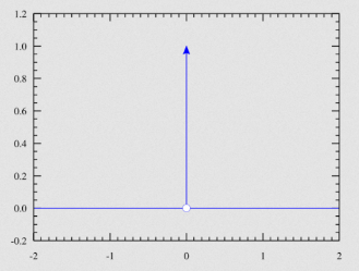
When there is a desired impulse response for a system, it directly implies a transfer function that is equal to the Laplace Transform of that impulse response.
5. Brune Synthesis Method
5. Brune Synthesis Method
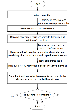
• The transfer function should be expressed as a rational function of the complex frequency variable . This means it has a polynomial numerator and a polynomial denominator:
s
Z(s)
N(s)
D(s)
• Here, and are polynomials in .
N(s)
D(s)
s
• The transfer function must be a positive real function, which implies certain mathematical properties that allow for physical realizability with passive components. Specifically:
• It must be real and non-negative for all real values of .
s
• It must have poles and zeros in the left half of the complex plane or on the imaginary axis.
• The degrees of the numerator and denominator polynomials will dictate the complexity of the network to be synthesized. Higher-degree polynomials correspond to more complex networks.
• A typical input might look like:
Z(s)+3s+2+2+s+1
2
s
3
s
2
s
• Such a rational function indicates the frequency-dependent behavior that the synthesized network should exhibit.
Algorithm Explanation
Algorithm Explanation
The Foster preamble involves the steps taken to prepare a positive real function for the Brune synthesis. The given positive real function should be represented as partial fractions. , Here, represents the initial expression, and different components of the polynomial correspond to various elements within the circuit. Specifically, if a portion of the polynomial takes the form s+, it signifies a capacitor and inductor connected in parallel. The remainder, denoted as , can undergo further expansion and iterations. The code which clearly displays the algorithm of Foster preamble is provided:
Z(s)s++s++(s)
k
∞
k
0
s
k
r
2
s
2
ω
Z
1
Z(s)
k
r
2
s
2
ω
Z
1
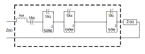
The “Safe extraction of Foster terms” section decomposes the expression into partial fractions and identifies monomials in the forms specified previously. Subsequently, it subtracts these extracted monomials from the original expression, preparing the remainder for further extraction and analysis.
This segment of the code delineates the extraction cycle. The process continues until both the reactance and susceptance lists are empty, indicating that no additional terms can be extracted. Upon reaching this condition, the cycle is terminated.
Z3 (s) now has a pole at infinity, which is removed to yield Z4 (s).
6. Examples
6. Examples
Here we can see and example of the Foster preamble function operating:
7. Demonstration and Results
7. Demonstration and Results
Displaying Generated Circuits
Displaying Generated Circuits