Method of Joints to Solve a Truss Problem
Method of Joints to Solve a Truss Problem

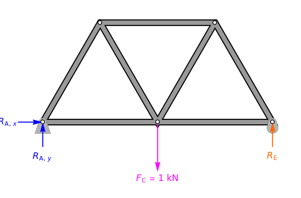
This Demonstration solves a truss using the method of joints, which involves doing force balances around one joint at a time.
1. Select "reaction forces" to see how the reaction forces and are calculated.
R
A
R
E
2. Then, under the drop-down menu, select "calculate moment" to see the moment balance around joint and calculate the reaction force at joint . Move the mouse over the equations to see an explanation of the moment balance.
A
E
3. Next, select "-force balance" to do a force balance in the -direction at joint . Note that joint is fixed but joint can move in the -direction.
x
x
A
A
E
x
4. Select "-force balance" to determine the reaction force at joint .
y
A
5. Select "balances at joints" and select joint . Check "focus on joint" to zoom in on the members around the joint and display the force balances. Note that the direction of the arrows are drawn in "focus on joint" because we know the correct direction. If the arrows were drawn assuming all members were under tension, then a negative force would result, indicating the direction should be reversed.
A
6. Repeat step 5 for the other joints.
7. When "solved" is selected from the joints, the compression (green) and tension (red) forces are shown on the full diagram. Arrows that point outward represent the member's response to compression forces, which act to shorten the member. Arrows that point inward represent the member's response to tension forces, which act to lengthen the member.
When doing balances around the joints, the signs on all of the forces are positive because we assume we can determine which members are under tension and which are under compression before solving the truss. This is done by starting at joint , seeing that the reaction force points upward and knowing that the member force must point downward for the truss to remain stationary.
A
Details
Details
First, calculate the reaction forces by doing a moment balance around joint and force balances in the and directions:
A
x
y
∑=0=w-2w
M
A
F
C
R
E
∑=0=
F
x
R
A,x
∑=0=-+
F
y
R
A,y
F
C
R
E
where and are the reaction forces at joint in the and directions, is the reaction force at joint , is the width of the members and is the point load force at joint .
R
A,x
R
A,y
A
x
y
R
E
E
w
F
C
C
Next, do force balances at the joints. The order of the calculations shown is the order that the joints are solved in. Calculations are done assuming we know which members are under tension and which are under compression. View the labeled truss in Figure 1 below.
Joint
A
∑=0=-sinθ+
F
y
F
AB
R
A
∑=0=-cosθ+
F
x
F
AB
F
AC
Joint
B
∑=0=sinθ-sinθ
F
y
F
AB
F
BC
∑=0=cosθ+cosθ-
F
x
F
AB
F
BC
F
BD
Joint
C
∑=0=sinθ+sinθ-
F
y
F
BC
F
CD
F
C
∑=0=--cosθ+cosθ+
F
x
F
AC
F
BC
F
CD
F
CE
Joint
D
∑=0=-sinθ+sinθ
F
y
F
CD
F
DE
Figure 1

References
References
[1] R. C. Hibbeler, Engineering Mechanics: Statics, 12th ed., Upper Saddle River, NJ: Prentice Hall, 2010.
[2] D. Morrell. Truss Example-Method of Joints (Edited)[Video]. (Jun 6, 2012) www.youtube.com/watch?v=56eTM36Z9-A.
Permanent Citation
Permanent Citation
Rachael L. Baumann, John L. Falconer
"Method of Joints to Solve a Truss Problem"
http://demonstrations.wolfram.com/MethodOfJointsToSolveATrussProblem/
Wolfram Demonstrations Project
Published: September 8, 2017