Building A Pulse Forming Network with the Wolfram Language
Building A Pulse Forming Network with the Wolfram Language
by Robert Mendelsohn
Introduction
Introduction
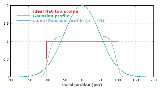
In many physics experiments, a voltage or current is desired which quickly rises to a particular value, stays there for a duration of time, and the declines rapidly, giving the so-called flat-top profile or square wave:
This has applications in a lot of physics and electrical-engineering related systems, including radar, kicker magnets for accelerators, and really anytime a pulsed uniform voltage or current is needed. In this post, I’ll walk you through some of the theory of pulsed forming networks, along with how I used the Wolfram Language to quickly and easily design a cost-effective pulsed forming network by using circuit theory, interactive Manipulate functionality and data from an electronics vendor to explore many practical design options. This will also show off the neat Quantity functionality of the Wolfram Language, which has proven to be really useful and easy to use.
Capacitors Discharging
Capacitors Discharging
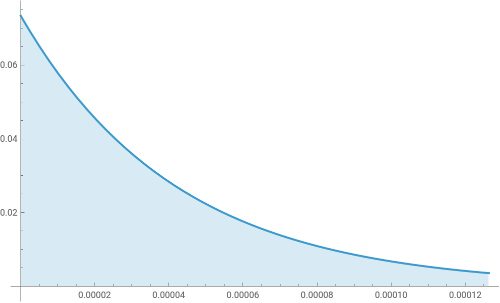
When people consider pulsed power applications, the natural and easy solution which comes to mind is to connect a capacitor in series with the load, charge it, and then discharge it. Assuming the capacitor’s inductance and series resistance is low, a large current can be created, but that current will rapidly -- indeed, exponentially -- decay:
Out[]=


What do we do to “flatten” the peak? Increasing the resistance or capacitance will stretch the above figure horizontally or vertically, but varying the resistance or capacitance will not alter the shape of the discharge curve. It is worth pointing out that there is one (conceptually) trivial solution here, which is to have a very very large capacitor, such that the capacitor will discharge only a minor fraction of its stored energy over the desired pulse width, and to use a switch to disconnect the circuit after the desired duration.
What about using a switch?
What about using a switch?
While this indeed would produce a very flat profile, it requires capacitances so large that only electrolytic double layer capacitors -- also called supercapacitors -- would work. Supercapacitors often have maximum voltages of around 2.7V, requiring a large number of them in series to get up to a larger voltage. Placing capacitors in series adds the respective equivalent series resistance of each capacitor as well as their inductances, often severely limiting the peak current. Additionally, semiconductor switches are limited in their ability to stop flowing currents, although the top-of-the-line transistors, like the IXTN660N04T4 (~$21) can switch around 700 amperes at around 40 volts. That may work for some applications, like an electromagnet system that requires modest voltages but high currents, but for most applications this will be prohibitively expensive and still have poor performance.
The LRC Circuit
The LRC Circuit
Getting back to the question - “how do we “flatten” the peak of a capacitor’s discharge curve?” - the answer is, simply, using inductors. Many inductors are simply wound coils of wire, and inductors tend to resist the change in current through them. They do this by storing the electrical energy in the form of a magnetic field. This is commonly compared to a capacitor, which stores electrical energy in an electrical field. Indeed, one of the most famous and important circuits of all time is the LRC-circuit (which stands for inductor, resistor, capacitor). If the resistance, capacitance and inductance are tunes properly, you can get resonant behavior where the capacitor and inductor are alternately charging and discharging.
Fourier Series
Fourier Series
This sinusoidal charge-discharge curve is really important and very useful to what we are building up to. In mathematics, you may have heard of a Fourier series, the idea behind which is that any harmonic function can be closely approximated by a series of superimposed sinusoidal functions. The pulse shape we are trying to generate is a square wave, and therefore we can use the Fourier series deconstruction of a square wave (or at least the first N terms) to determine a number of LRC circuits in series, which, when discharged approximate a square wave.
The Faults in our Fourier Series
The Faults in our Fourier Series
One important note is that using the Fourier series approximation to a perfect square wave has one serious downside: the Gibbs phenomenon, which more or less says that the edges of the Fourier-series approximation to a square wave will have significant overshoot, and adding more terms does not improve this issue. Some bright physicist determined that looking at Fourier series of a trapezoidal rather than square wave suitably solved these issues.
Finally: Pulsed Forming Networks
Finally: Pulsed Forming Networks
Alright, that’s probably enough theory. To recap, simply discharging a capacitor into a resistive load will give use a sharp rise with exponential decay, and adding an inductor will turn that discharge curve into a sinusoidal shape. Superimposing multiple sinusoidal discharges can create a pretty good approximation to an ideal “square” discharge curve. How should we arrange these capacitors and inductors?
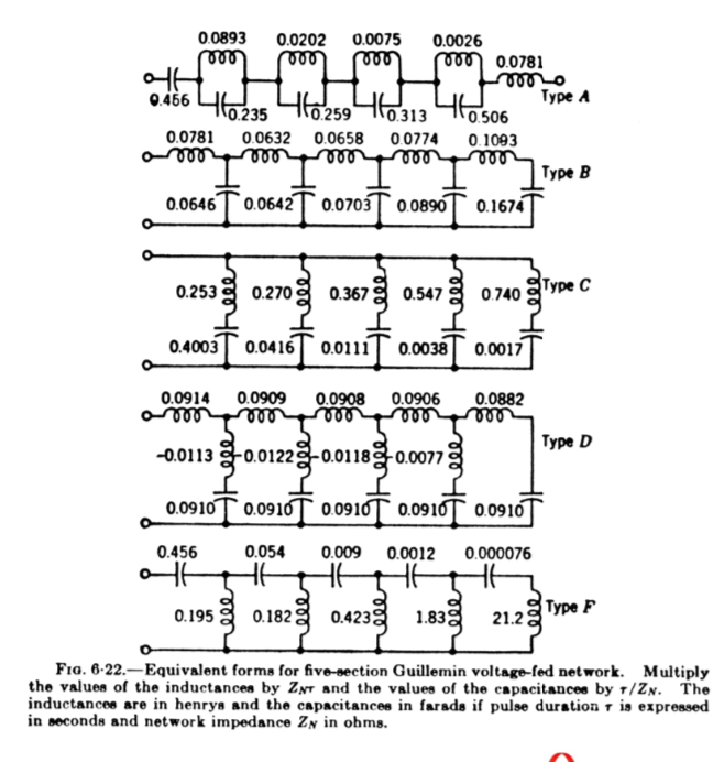
As it turns out, there are a lot of different forms of pulse forming networks, usually known by a letter. Many of these have a particular advantage; for example, the type D pulse forming network uses capacitors of identical capacitance. Because of this, you’ll have to consider your application in greater detail to decide which is best, which usually comes down to a decision of practicality: i.e. cost and ease of construction.
Practicalities of Building a Pulse Forming Network
Practicalities of Building a Pulse Forming Network
Depending on the voltage, current, rise time and pulse width requirements of a particular application, the difficulty can be found in a number of places. For fast rise times, the issue may be switching (a topic outside the scope of this article), or even the inductance of the capacitors. For high voltage applications involving high charge transfer, finding suitable capacitors may be very difficult and expensive. It really depends on the application, as well as available capacitor and switching technology. One last note: for most practical purposes, there are few benefits in using more than 5 sections.
Designing a Particular Pulse Forming Network
Designing a Particular Pulse Forming Network
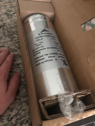
For the remainder of the article, we will be talking about pulse forming networks in the context of a particular project, which is an upgrade I am making to a metal vapor vacuum arc plasma source I have, which I built to study various aspect of metal plasmas. For this application, the switching is performed by the initiation of a vacuum arc by a Marx generator (if you’d like an article about Marx generators, mention it in the comments), so switching is not an issue. The main design considerations would be that there should be as fast a rise time as possible, and that the current should exceed 100 amperes throughout the pulse, and the homogeneity should be reasonably high. The voltage is modest - no more than 800 volts - and many film capacitors exist that can satiate the desired low ESR and ESL requirements. The major design difficulty will be the proper arrangement and choice of capacitors and inductors (necessarily a tradeoff between complexity, cost and performance), and the major implementation difficulty will be in making the inductors. Commercially available inductors that can handle the expected peak currents - possible in excess of a kiloampere - are prohibitively expensive, but making a large coil of thick wire will produce an inductor with high peak current handling capabilities on a budget, so long as the needed inductance is low. The desired rise time for this application is less than 500 nanoseconds and the pulse width, counted as the period where the current exceeds 100 amperes, is desired to be around 500 microseconds. One final caveat: a little while ago I pickedS up two giant power film capacitors in an auction. They are individually able to deliver a surge current of over 20,000 amperes, and for cost reasons, I’d like to use them rather get all new capacitors.
A Note About “DIY” Pulse Forming Networks
A Note About “DIY” Pulse Forming Networks
As far as I am aware, there is only one report on the internet of someone making a “DIY” pulse forming network - a gentleman who was trying to construct an amateur radar assembly. While the application considered here is not too complex, there are many circumstances, including very fast rise times, large charge transfer and high voltages that make professional pulse forming network design a challenging area. That being said, there’s no reason why they are any more difficult to build than various other resonant circuits. A word of caution: many of the things discussed here could be potentially dangerous if mishandled - don’t play around with high voltage. The voltages discussed here are potentially lethal and should only be handled by competent, cautious and safety-aware people.
The Type B Pulse Forming Network
The Type B Pulse Forming Network
When considering the aforementioned requirements, the natural first choice is the type B pulse forming network. It is typically the choice when you don’t want/need mutual inductance between the various inductors, and it has the neat feature of having two capacitors (left-most ones) that have reasonably similar capacitances, where my two 250uF capacitors could go.
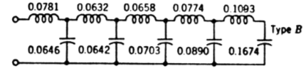
This is where the first difficulty is encountered: capacitors are typically rated at a particular granular capacitance; 250uF, not 263uF. There are capacitors which have odd capacitances, but they are sufficiently unusual that we have to design around which capacitances are available.
The diagram shows the ideal ratios of the capacitors, and right off the bat it doesn’t look to be too bad of a fit. The middle capacitor would need to be 300uF, followed by 350uF and 800uF, respectively, but it’s not that off. If you wanted to get really precise values, you could use multiple capacitors in parallel to form an equivalent capacitor of some fractionally higher value, but for this project you’ll soon see why that introduces unreasonable complexity and cost. So how would this circuit perform? When using the above diagram along with known load parameters, you get this circuit:
Which, when charged and discharged, produces the following discharge pattern:
While there is good homogeneity, there are four downsides to this arrangement:
1. the rise time is too slow, on the order of several thousand nanoseconds
2. the complexity is high, involving 5 large capacitors and 5 custom inductors
3. the increase in stored energy over the old system (straight discharge of the 2x250uF capacitors into load) is only about 4x
3. the cost is high for what it’s accomplishing; around $200 just for the capacitors (before tax and shipping)
Rethinking the Configuration, Computationally
Rethinking the Configuration, Computationally
At long last, after a long preamble, we can get into the real “meat” of this article. We have this interesting electrical engineering problem that is both theoretical and practical; can the Wolfram Language help us make a cost-effective decision?
To do this, let’s get some real-world data about the price and capability of existing capacitors. Then, we can create a little circuit simulator for these pulse forming networks which can give us some key information about the performance, cost and complexity of a circuit. Then we can have it simulate all possible circuits (within reason) and give us the top-ranked ones. Easier said than done, but it’s a nice computational approach and might give us an unexpected result. It would be too tedious to go through and try to figure this out manually, but it will likely take a modern processor seconds or minutes to step through all permutations.
To do this, let’s get some real-world data about the price and capability of existing capacitors. Then, we can create a little circuit simulator for these pulse forming networks which can give us some key information about the performance, cost and complexity of a circuit. Then we can have it simulate all possible circuits (within reason) and give us the top-ranked ones. Easier said than done, but it’s a nice computational approach and might give us an unexpected result. It would be too tedious to go through and try to figure this out manually, but it will likely take a modern processor seconds or minutes to step through all permutations.
Getting Data About Capacitors
Getting Data About Capacitors
I’ve found that the online electronics distributor Digikey has some of the best search tools, and they allow you to download large tables of data about their products. Here, I went to their page on film capacitors, and filtered out capacitors with a maximum working voltage under 800 volts, as well as capacitors with a capacitance under 500uF. I then downloaded a CSV of the remaining 151 capacitors.
Importing and Cleaning The Capacitor Data
Importing and Cleaning The Capacitor Data
One of the the best but rarely-mentioned aspects of the Wolfram Language is it’s great for scraping and homogenizing data. That’ll come in handy as we import the raw capacitor data and clean it up.
Here’s the fields and the first capacitor:
Let’s first filter out capacitors that aren’t in stock, or require more than 4 minimum order quantity:
Only 46 capacitors left. What about price? If a capacitor is too expensive, we shouldn’t consider it:
Let’s consider capacitors with a price below $125, since we will probably need 2-3 of them:
As a final step to pare down the list of capacitors, let’s allow only one capacitor per capacitance class. The equivalent series resistance of all of these options is quite low, so it’s not an important factor.
Last but not least, let’s get rid of the data we don’t really care about and get our final dataset:
An interesting way to visualize the cost-effectiveness of these capacitors is to examine their capacitance per dollar. In this respect, one capacitor in particular has a large advantage; the B25690A0128K903 offers 1200uF at only $60.76.
Pulse Forming Network Configuration
Pulse Forming Network Configuration
In order to optimize for complexity and cost, we’re going to consider a type C pulse forming network, with one caveat; in order to get very fast rise times, a capacitor will be attached without an inductor to the main load, so only the capacitor’s ESL will slow the rise time.
Configuration 2
Configuration 2
This is our first real pulse-forming circuit. It can be approximated as an RC circuit and a LRC circuit, which really simplifies the differential equations that govern it. A closed form solution is not possible, but we can use DSolve to get a solution to the differential equation:
For this configuration, there are two groups of capacitors. Let’s generate a list of all unique combinations of the possible capacitors, given the total (including the “free” 2x250uF capacitors I already have) cost of the new system is <$200:
Next, let’s simulate all of these configurations and see which ones do best. The key parameters to compute are:
-how long the pulse is above 100 amperes (desired to be greater than 250us but less than 1ms)
-the peak current (desired to be greater than 500A but less than 1.5kA)
-the cost (as small as possible)
-total energy of the circuit (as large as possible)
-homogeneity (high)
-how long the pulse is above 100 amperes (desired to be greater than 250us but less than 1ms)
-the peak current (desired to be greater than 500A but less than 1.5kA)
-the cost (as small as possible)
-total energy of the circuit (as large as possible)
-homogeneity (high)
From here, we can select a suitable arrangement. Of course, more complex topologies can deliver greatly improved performance. If you’d be interested in a Wolfram Language exploration of more complex topologies, leave a comment and I’d be happy to write it up. The Wolfram Language is a really amazing tool and it’s interesting how it was useful from theoretical consideration to scraping capacitor data and optimization through solving differential equations.