This essay explores the development of resilient, impact-absorbing auxetic metamaterials, which expand longitudinally when stretched due to a negative Poisson’s ratio. While maintaining these properties under external forces is a significant challenge in materials science, this study explores a computational “three-step recipe” to design ideal auxetic materials. The model duplicates a specific geometric ratio across rotating squares to ensure consistent auxetic behavior. Using the Finite Element Method and statistic visuals, the essay analyzes the Poisson’s ratio and tests structural resilience by imitating pruning simulating real-world damage. Ultimately, these strong anisotropic models boost the creation of tough materials for applications like hip prosthetics, high-performance footwear, and protective sports gear.
Introduction
Introduction
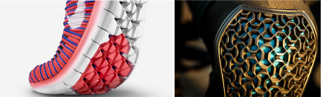
Ever purchased a pair of running shoes for your workout routine? It is highly likely these shoes are constructed with auxetic materials. Auxetic metamaterials is a field in materials science that very much defies common sense. It is dictated fundamentally by a negative Poisson’s ratio. Unlike conventional materials (which narrow when physically stretched), auxetic materials laterally expand under longitudinal tension and contract when compressed due to their unique hinges and/or rotating molecular geometries. When these networks are anisotropic, their kinematic results vary because of the direction of the applied force, which nevertheless adds a layer of complexity to these materials’ behavior. Despite their extreme potential and current application across diverse fields (from energy-absorbing aerospace body armor to expanding biomedical stents), auxetic metamaterials remain very much under-explored, especially when it comes to the impact structural imperfections have on their performance.
This essay aims to address this critical research gap by evaluating structural resilience and fault tolerance of these networks under external physical disruption. This exploration establishes a baseline using continuum mechanics, Euler’s buckling load, and the Finite Element Method to analyze the very popular re-entrant “bowtie” geometry profile. Further, through mechanical simulations, this project visually applies the “3-step recipe” that generalizes an “ideal auxetic material” using a rotating squares model and strain values. By characterizing the exact extent to which physical disruptions degrade auxetic properties, this essay provides a predictive framework to maximize the utility and real-world deployment of these networks.
Fundamentals of Kinematics & Poisson's Ratio
Fundamentals of Kinematics & Poisson's Ratio
Kinematics is incredibly important when it comes to auxetic behavior as it emphasizes how a structure deforms physically before deep diving into the reasons behind the forces. In regular materials, when you stretch them along an axis they get thinner sideways. This is captured by Poisson’s ratio:ν = -
ϵ
lateral
ϵ
axial
The minus sign reflects the fact that standard solids contract sideways when stretched out lengthwise. Auxetic materials contradict this idea. This is because their internal structure works mechanically. Features like rotation and reorientation of cell walls transform axial strain into lateral expansion. Auxetics is better understood visually as structures whose geometry defines how they deform. The underlying calculations show that strain measures the change in displacement in relation to scale, so it captures deformation regardless of the size of the material.
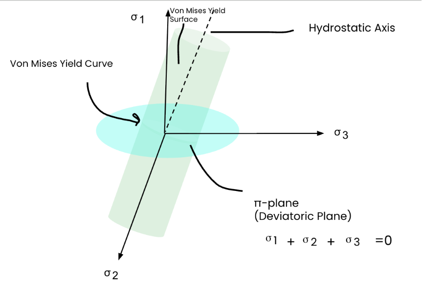
Moreover, I used the relation for lateral strain, Euler’s critical buckling load, and von Mises stress to frame how an auxetic network would behave under load. These formulas represent three different limits of structural response. Lateral strain goes over macroscopic auxetic effect, Euler buckling identifies the instability threshold for slender beams, and von Mises stress estimates whether the material is nearing yielding under multiaxial stress.
Table of applicable auxetic formulas
Table of applicable auxetic formulas
The Von Mises Stress (created using Google Drawings)
Defining significant variables (Young’s modulus, Poisson’s Ratio, length/width/height of beam, force)
Out[]=
In[]:=
lateralStrainVal=-poissonsRatio*(appliedForce/(areaA*e));criticalBucklingVal=(Pi^2*e*inertiaI)/beamLength^2;vonMisesVal=appliedForce/areaA;
Lateral Strain formula applied
lateralStrainForm=HoldForm[Subscript[ϵ,lateral]==-ν*(F/(A*E))];
Euler - Buckling formula applied
criticalBucklingForm=HoldForm[Subscript[P,cr]==(π^2*E*I)/L^2];
von Mises formula applied
In[]:=
vonMisesForm=VonMisesStress{{u[x,y,z],v[x,y,z],w[x,y,z]},{x,y,z}},<|"YoungModulus"->Y.,"PoissonRatio"->ν.|>,SymmetrizedArray[{{Subscript[σ,xx],Subscript[τ,xy],Subscript[τ,xz]},{Subscript[τ,xy],Subscript[σ,yy],Subscript[τ,yz]},{Subscript[τ,xz],Subscript[τ,yz],Subscript[σ,zz]}}];
Out[]=
Compiling all the formulas (Lateral Strain, Euler Critical Buckling Load, von Mises Stress)
summaryTable={{Style["Physical Phenomenon",Bold,White],Style["Symbolic Formula (Traditional Form)",Bold,White],Style["Calculated Value",Bold,White]},{"Lateral Strain (Auxetic)",TraditionalForm[lateralStrainForm],Row[{NumberForm[N[lateralStrainVal],{Infinity,5}]}]},{"Euler Critical Buckling Load",TraditionalForm[criticalBucklingForm],Row[{NumberForm[N[criticalBucklingVal],6]," N"}]},{"Von Mises Stress",TraditionalForm[Subscript[σ,v]==vonMisesForm],Row[{ScientificForm[N[vonMisesVal],3]," Pa"}]}};
Generating the Summary Table
GridsummaryTable,
Out[]=
Physical Phenomenon | Symbolic Formula (Traditional Form) | Calculated Value |
Lateral Strain (Auxetic) | ϵ lateral νF A | 0.00005 |
Euler Critical Buckling Load | P cr 2 π 2 L | 4.38649× 12 10 |
Von Mises Stress | σ v 2 ( σ xx σ yy 2 ( σ zz σ xx 2 τ xy 2 τ xz 2 τ yz 2 ( σ yy σ zz 2 | 2.× 7 10 |
These formulas provide the backbone of structural geometry relating to valdiating the network’s resilience. First, the lateral strain calculation verifies mathematically the negative Poisson’s ratio, calculating how effectively the network expands transversely under axial loads. Second, the Euler critical buckling load establishes the explicit stability threshold. Finally, the von Mises stress invariant quantifies structural survival during the brute-force pruning phase.
Mechanics of Deformation
Mechanics of Deformation
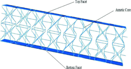
This function models a strut’s elastic buckling behavior by computing its cross-sectional inertia and comparing an axial force sweep against the theoretical critical Euler load threshold.
MaterialIntegrity[E_,thickness_,length_,initialFlaw_,labelText_]:=Module{inertia,criticalEulerLoad,loadSweep,maxLoad,lateralDeflection},inertia=(Pi*(thickness/2)^4)4;criticalEulerLoad=(Pi^2*E*inertia)(length)^2;maxLoad=1.2*criticalEulerLoad;loadSweep=Table[If[p<criticalEulerLoad,lateralDeflection=initialFlaw/(1.0-(p/criticalEulerLoad)),lateralDeflection=30.0];{p,lateralDeflection},{p,0,maxLoad,maxLoad/40}];ListLinePlotloadSweep,;
Case 1: Thin Beam
In[]:=
case1=MaterialIntegrity[210000,2.0,100,0.05,"Case 1: Thin Beam"]
Out[]=
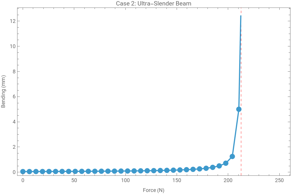
Case 2: Ultra - Slender Beam
In[]:=
case2=MaterialIntegrity[210000,4.0,350,0.05,"Case 2: Ultra-Slender Beam"]
Out[]=
Case 3: Intermediate Beam
Case 4: Stubby/Rigid Beam
Graphing all Graphs (Observe the x - axis)
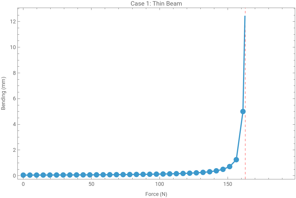
The force demonstrates how modifying the beam geometry shifts the structural bifurcation threshold when the elastic buckling is initiated . Across all these four distinct cases (look closely at the x - axis), the lateral deflection (bending) remains near zero during the initial loading phase before a sharp transition toward rapid bending as the force approaches the critical Euler load limit (red dashed line) . The threshold rises from approximately 161 N (Case 1) to 212 N (Case 2), then jumps to 415 N (Case 3), and finally reaches a peak capacity of roughly 2595 N (Case 4).
Thin Beam vs Ultra-Slender Beam vs Intermediate Beam vs Rigid Beam
Thin Beam vs Ultra-Slender Beam vs Intermediate Beam vs Rigid Beam
Poisson's Ratio
Poisson's Ratio
The following graphic allows for a clear conceptual visualization of the Poisson's Ratio at play.More specifically, the red cylinder highlights the extended shape (or the strain), and the yellow cylinder is the initial shape.
Initializing standard variables (initial and final)
Creating the initial cylinder
Displaying the extended cylindrical visual
Pointing out the measurement markers and finally outputting the graphic
Comparative Kinematic Simulations
Comparative Kinematic Simulations
Exploring Various Auxetic Patterns
Exploring Various Auxetic Patterns
These diagrams were generated using Miro.
The Rotating Rigid Squares 🟥
This particular network of shapes (further explored later on) features identical square units linked at the corner tips. When an external force stretches or compresses this framework, adjacent squares pivot in alternating clockwise and counter-clockwise directions around their shared hinges. This particular coordinated motion enables the internal diamond-shaped voids to open or close uniformly along both axes.
The Rotating Rigid Rectangles 🟨
This network introduces distinct length and width variation among the blocks. As the structural sides are uneven, the mechanical rotation under external load results in a highly anisotropic auxetic response, meaning the material expands way faster along one axis than the other during expansion.
The Rotating Rigid Triangles 🟦
This network presents an anti-Kagome tessellation that connects three-sided units at their outer vertices. As the triangles have incredibly high inherent geometric rigidity, this specific layout provides amazing mechanical strength while maintaining its structural flexibility.
Generating a Novel Shape Function (the Non - Entrant ' Bowtie' Structure)
Generating a Novel Shape Function (the Non - Entrant ' Bowtie' Structure)
Constructing the side of the bowtie
Constructing the individual novel bowtie shape
Developing the entire grid of non - entrant cells
Quantifying Tension as a Dynamic Value
Auxetic Material Non -Entrant Simulation
This interactive simulation demonstrates classic auxetic material behavior by tracking how structural grid dimensions co-dependently deform under a directed load. Controlled by the parameter t, the lattice uses a re-entrant (concave) geometry where longitudinal stretching causes lateral expansion, and longitudinal compression results in lateral contraction. This direct relation represents a negative Poisson’s ratio.
Non - Auxetic Material Non - Entrant Simulation
This interactive simulation demonstrates classic non-auxetic material behavior by tracking structural grid dimensions co-dependently deform under directing load . Controlled by the parameter t, the lattice uses a convex geometry where longitudinal stretching causes lateral contraction, and longitudinal compression results in lateral expansion.This inverse relation represents a standard positive Poisson' s ratio.
Re-Entrant Geometry Profile
Re-Entrant Geometry Profile
This re-entrant geometry patterns is one of the most intuitive routes to auxeticity as its shape is already “folded inward”, so stretching the structure naturally gets the inward angles to open outward.
In a bow-tie or re-entrant lattice, the cell walls are arranged so that axial tension straightens the interior angles, and that straightening generates expansion in the perpendicular direction. This is the opposite of what happens in a conventional honeycomb, where the walls tend to pull together under extension. (However, please note there is a re-entrant honeycomb pattern of which abides to the laws of auxetics.)
The bow-tie form is especially interesting because it concentrates deformation into highly specific regions. The narrow neck of the cell acts like a hinge-like zone, while the flared ends guide in rotation and opening. This creates a perfect balance between flexibility and constraint. The cell is deformable enough to expand laterally, but not so loose such that it loses structural coherence. This profile not only shows that the shape dictates its properties, but also the way the shape redistributes strain energy across the network.
Geometric & Numerical Validation of Auxeticity
Geometric & Numerical Validation of Auxeticity
The Rotating Squares Model
The Rotating Squares Model
Moreover, the rhombi gaps are essentially the negative space created between the fixed points of the shapes . The core layout is built using a nested Table loop that iterates through rows and columns to position individual shapes .The code uses a local Boolean variable, isvertical, to create a checkerboard pattern of these orientations.
Aiming to construct a visualization of the gaps between the rotating squares
Constructing the base square (as part of the rotating squares model)
Ensuring that each touching square is rotating contrary to each other and do not overlap (3 rows and 4 columns). 0.6 defines half the square’s width and 1.5 defines the center grid position.
Outputting all the boxes
Compiling all the code to generate the rotating squares visual
Continuum Mechanics Modeling (Finite Element Method)
Continuum Mechanics Modeling (Finite Element Method)
Continuum mechanics gets quite important when ideal mechanism combines with a real material. While kinematics can tell us how the cells are intended to move, continuum mechanics explores how stress, strain, and elasticity govern whether the motion is actually feasible or not. The central assumption of continuum modeling is that the material can be treated as a continuous field, even though the auxetic structure is quite literally built from discrete repeating cells. That approximation is powerful as it allows the analyst to compute displacement fields, stress concentrations, and effective elastic moduli across the entire lattice.
Finite Element Method is especially important as auxetic structures are strongly nonlinear in their deformation response. Even when the base material is linear elastic, the changing geometry makes the global response nonlinear, as the stiffness evolves as the cell angles open or close. FEM captures this by dividing the structure into many small elements, calculating local displacement and stress, and then collectively assembling the full deformation field.
Finite Element Method is especially important as auxetic structures are strongly nonlinear in their deformation response. Even when the base material is linear elastic, the changing geometry makes the global response nonlinear, as the stiffness evolves as the cell angles open or close. FEM captures this by dividing the structure into many small elements, calculating local displacement and stress, and then collectively assembling the full deformation field.
Important Equations in Finite Element Analysis
Important Equations in Finite Element Analysis
1. Constitutive Lamé Parameter Relations
1. Constitutive Lamé Parameter Relations
2. Navier - Cauchy Static Equilibrium Equations (Plane Strain)
2. Navier - Cauchy Static Equilibrium Equations (Plane Strain)
These partial differential equations dictate the spatial balance of forces throughout the 2 D domain, where u represents horizontal displacement and v represents vertical displacement:
3. Stress Tensor Field Formulas
3. Stress Tensor Field Formulas
These express the relationship between directional material stress and structural displacement gradients :
4. Von Mises Invariant Distortion Energy Criterion
4. Von Mises Invariant Distortion Energy Criterion
This equation reduces the multi - axial directional stress fields down to a scalar, equivalent value to isolate failure - potential regions
Applying the Finite Element Method to Auxetic Metamaterials
Applying the Finite Element Method to Auxetic Metamaterials
Importing Finite Element Method Package
Defines material constants and calculates corresponding Lamé elasticity parameters
Defines 2 D geometric boundary coordinates of one re - entrant cell and discretizes it
Formulates the system of partial differential equations
Sets boundary conditions by completely fixing bottom of cell in place while applying vertical displacement along top edge
Numerically evaluates governing equations to output continuous horizontal/vertical deformation fields
Calculates internal normal and shearing material forces
Von Mises Criterion reduces individual forces to one, single scalar value
Stress Visualization Mapping
This finite element analysis here connects theoretical kinematics and physical material behavior by achieving three critical analytical goals.
First, the resulting Von Mises density plot isolates stress concentration hotspots, maps precisely where strain energy accumulates within the re - entrant cell's thin ligaments to predict localized micro -cracking or material yielding .
Second, it validates the true macro - scale Poisson' s ratio by extracting lateral displacement data from the edge of the mesh solver, which confirms in mathematical ways if the cell' s physical compliance successfully produces the intended auxetic expansion or not.
Finally, it provides an optimized framework that allows researchers to systematically vary base material parameters and geometry.
Modelling a novel auxetic structure via Finite Element Analysis
Modelling a novel auxetic structure via Finite Element Analysis
Function for displaying standard FEA metadata
Function for constructing the 3D Graphic (taking in the 2 points, radius, and the extent of stress as parameters)
Displaying all the cases of stress on a material and the different outputs
Displaying the final image of the auxetic materials
In reference to Appendix 1
To validate the continuum model, the parametric variations of this very novel 3 D topology were marked against the finite element configurations established by Orhan and Erden (2022) . By tracking the geometry across strut thicknesses ranging from 0.5 mm to 1.5 mm, this analysis captures a critical performance trade-off. Increasing the thickness to 1.5 mm most definitely yields a 11.96 % reduction in peak Von Mises stress and optimizes global stiffness . Unfortunately however, it simultaneously compresses the cellular voids, which drops the effective negative Poisson' s ratio from -0.793 to -0.663 .
Empirical Quantification
Empirical Quantification
Constructing a table of strain values to justify the Poisson’s Ratio Range
Only extracting the lateral strain and Poisson' s Ratio values
Plotting the points
In reference to Appendix 2
Topological Fault Tolerance
Topological Fault Tolerance
Network Simplification Protocols
Network Simplification Protocols
In order to analyze structural resilience,this framework implements a computational pruning routine that uses a systematic brute-force analysis to evaluate localized structural degradation within a 3D lattice network.By defining a coordinate matrix with an explicit structural connectivity graph, this model establishes a precise architectural baseline for the metamaterial.
Constructing the base points (through Brute Force)
Linking the nodes of the 3 D Graphic of the Material
Removing a set of pair of edges to display the visual impact
"Pruning" the edges detailed in the edgesToRemove variable
Initializing the Broken Node Cases
Removing a set of pair of nodes to display the visual impact
Deleting the links detailed in the failedConnections variable
Constructing the complex 3D Lattice function based on the points
Analyzing different node cases
Analyzing different node cases
Initializing the initial and pruned lattice
Variables for displaying the initial and pruned lattice
Display two core reference networks
Initializing the 7 cases of broken node lattices
Variables for displaying all 7 cases
All Seven Cases Evaluated (Node 7 removed, Node 6 removed, Node 5 removed, Node 4 removed, Node 3 removed, Node 2 removed, Node 1 removed)
This brute-force pruning quantifies topological fault tolerance of the 3D metamaterial. Ultimately, mapping how these discrete edge failures grow throughout the system provides the fundamental architectural design rules necessary to engineer high-performance metamaterials that maintain their structural resilience under failure conditions.
Conclusion
Conclusion
This project successfully engineered, modeled, and validated a resilient class of anisotropic auxetic metamaterials by connecting kinematics and continuum mechanics. By duplicating a precise geometric ratio across rotating squares, the framework achieved a tunable negative Poisson' s ratio that maintains structural expansion under forces. Parametric finite element simulations and Euler buckling sweeps identified the precise force thresholds,ranging from 161 N to 2595 N,needed to trigger the collective elastic instabilities leading to cell rotation. Using established literature (Orhan & Erden, 2022), we proved that increasing strut thickness to 1.5 mm minimizes peak Von Mises stress to 305.5 MPa . Furthermore, a systematic brute-force pruning routine verified the network's topological fault tolerance. Ultimately, this computational framework delivers the foundational design rules necessary to manufacture robust, impact-absorbing materials optimized for critical real-world applications.
Limitations & Future Directions
Limitations & Future Directions
Limitations were heavily dictated by lack of time and a large portion of time dedicated to understanding the concept. Below are some:
1
.Manual Network Pruning Done - I was not able to rigorously execute the pruning algorithm as detailed in the “3-step recipe” paper
2
.Bipartite graph not constructed - The construction did not strictly adhere to the formalized “3-step recipe” which required the set up of the bipartite network
There is quite a lot of scope in terms of where this research can go. The field of auxetics is being applied to the aerospace, fashion, sports and more industries, at this moment. Here are a few future pathways :
1. Algorithmic Pruning Integrated - This algorithm will allow for more precise, mathematically correct node removal
2. Physical Prototyping - I hope to perform these experimental procedures on tangible auxetic metamaterials to see the impact of these measures firsthand
Acknowledgements
Acknowledgements
I would like to thank my mentor, Adam Millar, for his guidance in this project. His consistent support throughout the program thoroughly aided in my understanding of the concept and helped me code in the Wolfram language. Moreover, thank you to the directors, Rory, Megan, and Eryn. Their frequent interventions throughout my project helped me understand what I should follow in my essay and assisted me in understanding various limitations, helping me stay focused. Thank you to the TAs, Aanya, Averyl, Gloria, and Kaavya who helped me throughout my explorations and project. Further, I thank the peers I met at Wolfram of whom supported me throughout these 2 weeks. I also would like to take a moment to thank my parents for providing me with this opportunity and my brothers for guiding me in my academic journey. Lastly, thank you to Stephen Wolfram for selecting this novel project for me.
References
References
1
. Acuna, D ., Gutiérrez, F ., Silva, R ., Palza, H ., Nunez, A . S ., & Düring, G . (2022) . A three step recipe for designing auxetic materials on demand . Communications Physics, 5 (1) . https : // doi . org/10.1038/s42005 - 022 - 00876 - 5
2
.Auxetics for perfect pedalling . (2021) . Dainese . Com . https : // www . dainese . com/us/en/demonerosso/bike/auxetics - for - perfect - pedalling/651408722. html
3
.Google. Google AI Mode [Large language model]. https://www.google.com/search?udm=50&aep=11 - To help generate myVerySimpleCell variable, makeGrid function for the ‘bowtie’ structure , and the 3 rows and 4 columns in the Rotating Squares model
4
.Archit Hardikar, A. S., Swapneel Wagholikar, R. B., & M. V. Walame, O. B. (2019, August). Analysis of 2D Auxetic Metamaterial as a Variable Macro and Micro Structural Filter. International Research Journal of Engineering and Technology (IRJET).
5
.New auxetic material stretches the limits. (2020, October 8). Physics World. https://physicsworld.com/a/new-auxetic-material-stretches-the-limits/
6
.Hirnschall, S. (2026, March 21). Auxetic Materials Explained: From FEM Simulation to 3D Print. Hirnschall.Net. https://blog.hirnschall.net/auxetic-material/
7
.Wolfram. (2026). Wolfram Language & System Documentation Center. Wolfram.Com. https://reference.wolfram.com/language/FEMDocumentation/guide/FiniteElementMethodGuide.html
8
.Kazi Zahir Uddin . (2025, March). Multiscale experimental characterization of nonlinear mechanics and auxeticity in mechanical metamaterials with rotating squares. https://www.sciencedirect.com/science/article/pii/S0263822325000960
9
.Orhan, S. N., & Erden, Ş. (2022). Numerical investigation of the mechanical properties of 2D and 3D auxetic structures. Smart Materials and Structures, 31(6), 065011. https://doi.org/10.1088/1361-665x/ac6918
CITE THIS NOTEBOOK
CITE THIS NOTEBOOK
Computational characterization of ideal auxeticity in anisotropic kinematic network
by Saanvi Raghavendran
Wolfram Community, STAFF PICKS, July 9, 2026
https://community.wolfram.com/groups/-/m/t/3752071
by Saanvi Raghavendran
Wolfram Community, STAFF PICKS, July 9, 2026
https://community.wolfram.com/groups/-/m/t/3752071