I am pleased to announce another package in my suite of applications for civil engineers, TerraPercalatio - A solution for groundwater flow. TerraPercolatio is a Wolfram Language paclet for modeling groundwater flow, constructing flow nets, and analyzing pore water pressure across complex soil geometries. You can find more details, documentation, and installation instructions on the TerraPercalatio paclet repository page. See last section for all related packages in this suite.
Engineers frequently have to deal with water in the ground, whether it is dealing with water inflow into an excavation, seepage pressures within a slope or designing drainage. TerraPercolatio has been designed for that. It is a general 2D steady-state seepage solver for multi-layer anisotropic materials, both confined and unconfined flow and produces true flow nets from the exact dual (stream-function) problem.
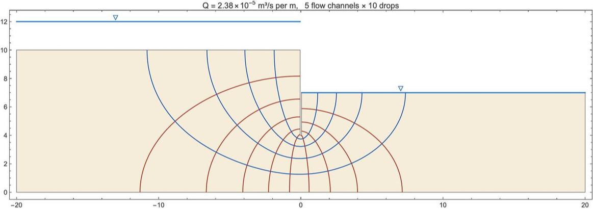
Used for drawing flownets and pwp. diagrams it including examples for most cases an engineer will encounter in practice. For example, a sheeted excavation in multi layered anisotropic soil.
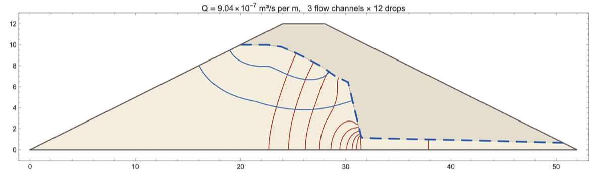
Hee is a zoned earth dam with a clay core
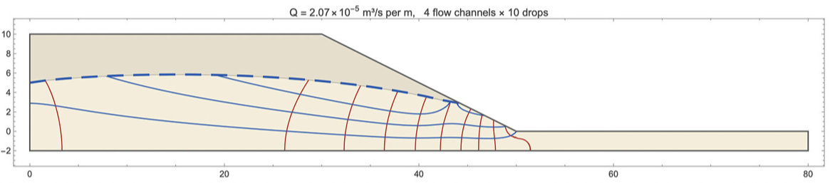
An important class of problem is unconfined flow within a slope. here is a simple example that includes recharge through rainfall.
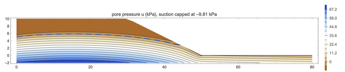
Suction can be taken into account when calculating porewater pressures.
Flow to a rectangular excavation.
Other examples covered include flow to a pumped well and groundwater lowering by wellpoints or drainage trenches.
TerraPercolatio[] is freely available as a function in the Wolfram function repository as an installable .paclet . At
https://resources.wolframcloud.com/PacletRepository/resources/MalcolmWoodruff/Framica/
TerraPercolatio[] is freely available as a function in the Wolfram function repository as an installable .paclet . At
https://resources.wolframcloud.com/PacletRepository/resources/MalcolmWoodruff/Framica/
Examples
Examples
Load the package after installing
Needs["MalcolmWoodruff`TerraPercolatio`"]
Example 1 — Flow into a dewatered excavation behind sheet piles
Example 1 — Flow into a dewatered excavation behind sheet piles
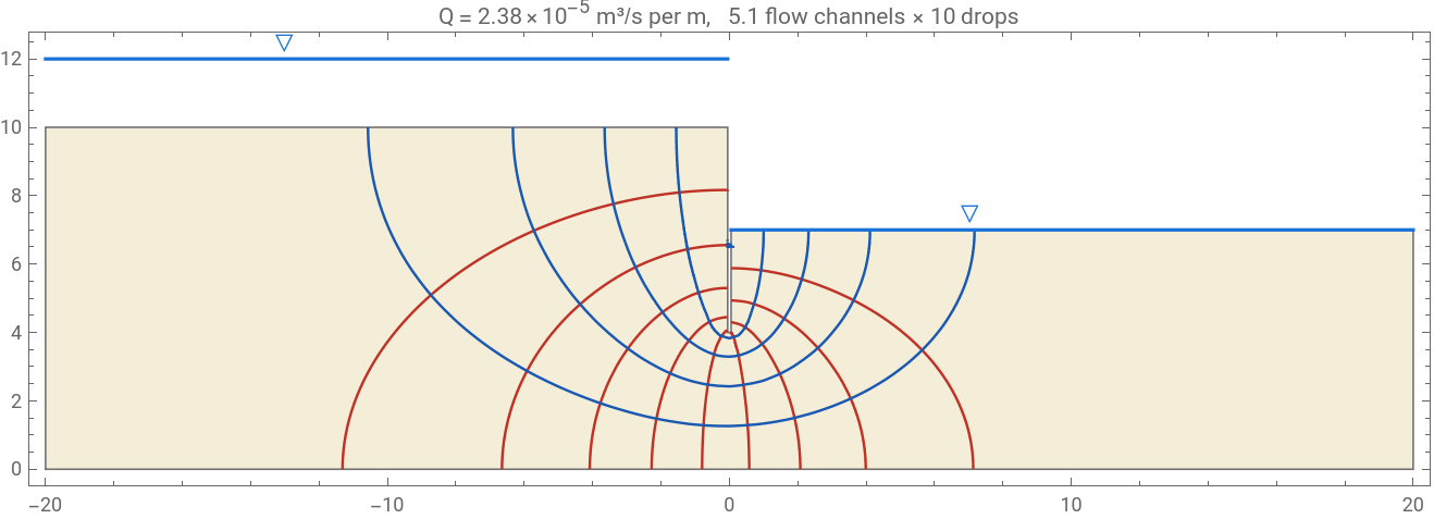
A sheet-pile wall (modelled as a thin slit) retains a 3 m deep excavation in a 10 m permeable stratum over an impermeable base. Upstream there are 2 m of standing water above ground level; downstream the ground is excavated to 7 m and dewatered, so the water level in the excavation coincides with the excavated ground level. All parameters are named below.
In[]:=
gUp=10.;(*upstreamgroundlevel,m*)gExc=7.;(*excavatedgroundlevel=waterlevelintheexcavation,m*)hUp=12.;(*upstreamwaterlevel:2mstandingwateraboveground,m*)hDn=gExc;(*downstreamhead:excavationdewateredtofloorlevel,m*)ytip=4.;(*piletipelevation:6mbelowu/sground,3mbelowfloor,m*)w=0.05;(*half-thicknessofthepileslit,m*)L=20.;(*lateralextentofthemodeleithersideofthewall,m*)kSand=1.*^-5;(*isotropicpermeability,m/s*)excPoly={{-L,0.},{L,0.},{L,gExc},{w,gExc},{w,ytip},{-w,ytip},{-w,gUp},{-L,gUp}};excLayers={<|"Polygon"->excPoly,"kx"->kSand,"ky"->kSand|>};excHeadBCs={{hUp,Function[{x,y},y>=gUp-10.^-6&&x<=-w]},(*u/sgroundsurface*){hDn,Function[{x,y},y>=gExc-10.^-6&&x>=w]}};(*excavationfloor*)pilePred=Function[{x,y},Abs[x]<=w+10.^-6&&y>=ytip-10.^-6];(*wall=streamline*)outerPred=Function[{x,y},y<=10.^-6||Abs[x]>=L-10.^-6];(*base&farfield*)excSol=SeepageSolve[excLayers,excHeadBCs,{pilePred,outerPred},"MeshSize"->0.4];excSol["Q"]
Out[]=
0.000023826
The "WaterLevels" option draws free-water surfaces (with the ▽ symbol), including standing water above ground — here the 2 m of ponded water upstream and the water held at floor level in the excavation:
In[]:=
FlowNet[excSol,"WaterLevels"->{{hUp,{-L,-w}},{hDn,{w,L}}},PlotRange->{{-L-0.5,L+0.5},{-0.5,12.8}},ImageSize->900]
Out[]=
Exit gradient across the excavation floor next to the wall (piping/heave check — compare with icrit ≈ 1):
In[]:=
ExitGradient[excSol,Function[{x,y},y>=gExc-10.^-3&&w+0.01<=x<=3.]]
Out[]=
0.427689
In[]:=
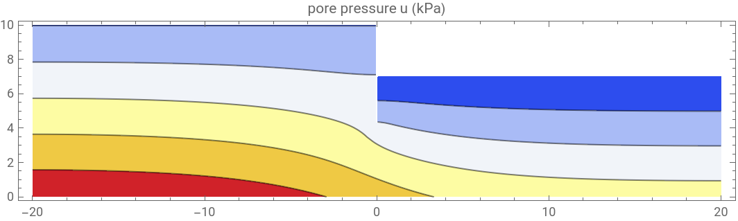
SeepagePlot[excSol,"PorePressure",ImageSize->600]
Out[]=

Example 1b — Same excavation, two-layer anisotropic soil
Example 1b — Same excavation, two-layer anisotropic soil
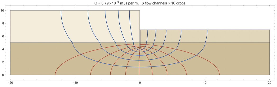
The stratum below 5 m is finer and anisotropic (kx = 2×10^-6, ky = 5×10^-7 m/s). Adjacent layer polygons must share vertices along interfaces; a layer interrupted by the wall is supplied as two polygons with the same k. Note the streamline refraction at the interface.
Example 2 — Unconfined flow through a homogeneous earth dam
Example 2 — Unconfined flow through a homogeneous earth dam
A 12 m high dam with 1V:2H slopes and a 4 m crest retains 10 m of water. The phreatic surface (dashed) and the exit point on the downstream slope are found iteratively; the seepage face below the exit point gets the h = y condition automatically.
Example 2b — Zoned dam with a clay core
Example 2b — Zoned dam with a clay core
Same dam with a central low-permeability core (k = 5×10^-8 vs 10^-5 m/s shells). Layers are listed in priority order — the first polygon containing a point supplies its conductivity. Nearly all head is dissipated across the core and the phreatic surface plunges to a low level in the free-draining downstream shell.
Example 3 — TerraLapsus slope: seepage through a 1:2 slope
Example 3 — TerraLapsus slope: seepage through a 1:2 slope
A 10 m high 1V:2H slope. The upstream water table stands 5 m above toe ground level (i.e. 5 m below the upper ground surface); downstream the water is at ground level. The impermeable model base is 2 m below the base of the slope. The datum (y = 0) is the downstream ground level at the toe. All parameters are named below; the solver finds the phreatic surface, the seepage-face exit point on the slope, and Q. For comparison, Dupuit gives Q ≈ k (hu² - hd²)/(2 Lflow) with saturated thicknesses measured from the base.
The phreatic surface and pore pressures below it can be passed straight to a slope-stability analysis (e.g. TerraLapsus):
Example 3b — Rainfall on the slope (raised water table, unsaturated zone)
Example 3b — Rainfall on the slope (raised water table, unsaturated zone)
Surface infiltration is added to any unconfined problem with "Rainfall" in mm/day (or "Recharge" in m/s). The rain is assumed to percolate vertically through the unsaturated zone and recharge the water table beneath, so it raises the water table and the pore pressures — the driver of most rainfall-induced slope failures. The water table is capped at the ground surface (excess is shed as runoff); the gap between them is returned as "UnsaturatedZone" and shaded in the flow net. Re-using slopeSpec from Example 3, compare dry ground with 20 mm/day of rain:
"UnsaturatedThickness" is {min, max} of the gap between water table and ground; when the minimum falls to zero the water table daylights on the slope face ("WaterTableDaylights" -> True) and that stretch becomes a runoff/seepage face. Increase the rainfall until it daylights to find the critical intensity for the slope.
Example 3c — Named problems and a pore-pressure map with suction
Example 3c — Named problems and a pore-pressure map with suction
Pass "Name" -> "id" to any solver to store its result under TerraPercolatio["id"]. Several independent problems can then coexist in one notebook and re-running one never disturbs the others — no shared state, no variable clashes. Here the dry and wet slopes are stored side by side:
A pore-pressure map of an unconfined solution now extends above the water table into the unsaturated zone, contouring the negative pore pressure (suction) clipped to "SuctionCap" metres of head (default 1 m ≈ 9.81 kPa) — the tension cut-off used in slope stability. Blue is positive pressure below the dashed water table, brown is suction above it:
Example 3d — Anisotropic slope with a thin permeable drainage seam
Example 3d — Anisotropic slope with a thin permeable drainage seam
A strongly anisotropic slope soil (kx = 1×10^-7 m/s, ky = 1×10^-9 = 0.01 kx, so flow is almost horizontal) contains a thin, highly permeable seam from y = 4 to y = 4.5 (kx = ky = 1×10^-5, 100× the bulk kx) that acts as an internal drainage layer. Layers are searched in order, so the seam polygon (listed first) takes priority inside its band and the bulk soil fills the rest. Because the unconfined multi-layer solver uses pointwise conductivities on a single mesh, a small "MeshSize" is given to resolve the 0.5 m seam.
Flow net: streamlines crowd into the seam and the equipotentials refract sharply across it — most of the discharge is carried horizontally along the seam to the toe. (Some streamline raggedness across the 0.5 m seam is the pointwise-k mesh resolving a 100–10000× contrast; refine "MeshSize" to smooth it.)
The total-head map shows the consequence for stability: above the seam the tiny ky keeps the head high (water perched, drains only slowly), while the seam concentrates the head drop and relieves the slope below it.
Example 3e — Slope under rainfall: pore pressures for a stability analysis (TerraLapsus)
Example 3e — Slope under rainfall: pore pressures for a stability analysis (TerraLapsus)
This ties the slope work together into an output for a limit-equilibrium stability program such as TerraLapsus, using the anisotropic slope with the permeable drainage seam from Example 3d. The slope is run under steady rainfall (mm/day), which raises the water table; the pore-pressure field is then the input the stability analysis needs. PorePressureField[sol] returns u[x,y] in kPa — the FEM value below the water table and capped hydrostatic suction above it, with a tension cut-off at "SuctionCap" metres of head (default 1 m). Sampling it on a grid gives a pore-pressure field to import; the phreatic line is exported too as a piezometric surface.
Physics note: rainfall can only infiltrate as fast as the soil's vertical permeability ky allows. If the applied rainfall exceeds ky the water table mounds unrealistically (the surplus should run off), so the base soil here uses ky = 0.1 kx (1×10^-7 m/s) with rainfall 5 mm/day ≈ 5.8×10^-8 m/s < ky. With the near-impermeable ky of Example 3d, rain would simply run off.
Physics note: rainfall can only infiltrate as fast as the soil's vertical permeability ky allows. If the applied rainfall exceeds ky the water table mounds unrealistically (the surplus should run off), so the base soil here uses ky = 0.1 kx (1×10^-7 m/s) with rainfall 5 mm/day ≈ 5.8×10^-8 m/s < ky. With the near-impermeable ky of Example 3d, rain would simply run off.
The pore-pressure map used for the stability check: positive pressure (blue) below the dashed water table, capped suction (brown) above it. Raise "SuctionCap" to allow more suction, or set it to a tiny value for no tension.
Build the pore-pressure grid and the piezometric line, and write them to CSV for import into TerraLapsus (u in kPa; divide by 9.81 for pressure head in metres). Only points inside the soil body are written.
Example 4 — Axisymmetric flow to a pumped well (drawdown cone)
Example 4 — Axisymmetric flow to a pumped well (drawdown cone)
Unconfined radial flow to a fully penetrating well in an aquifer on an impermeable base, solved in (r, z). SeepageWell finds the phreatic surface (cone of depression) and the seepage face on the well screen (between the pumped water level and the exit point) iteratively; the Stokes stream function from the dual problem gives flow tubes of equal discharge. Compare Q with the Dupuit-Thiem formula π k (H² - hw²)/ln(R/rw), which ignores the seepage face. All parameters are named below.
The seepage face on the screen runs from the well water level (▽, 8 m) up to the exit point (≈14.2 m). Equal head drops fall at geometrically spaced radii, as radial-flow theory requires. Axes are (r, z); the plot is zoomed to r ≤ 60 m.
Example 5 — 3D flow into a rectangular excavation
Example 5 — 3D flow into a rectangular excavation
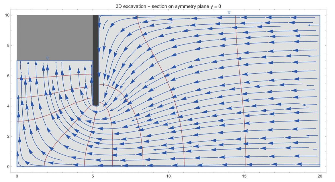
A 10 m × 16 m excavation behind sheet-pile walls, dewatered to a floor 3 m below ground, in a 10 m stratum over an impermeable base. One quarter is modelled with symmetry planes at x = 0 and y = 0 (both natural no-flow boundaries). The walls and the excavated void are subtracted from the domain by constructive solid geometry, so wall faces are true no-flow boundaries. The far-field water table is held at ground level. All parameters are named below.
Total inflow (4 × the quarter-model flux through the floor) and exit gradients on the floor — note the 3D result that the pit corner is more critical than mid-wall:
Section on the symmetry plane y = 0: equipotentials (red), streamlines (blue), water levels (▽) at ground level far away and at floor level in the pit:
Plan view of the piezometric drawdown at mid-depth below the floor — rectangular near the pit, becoming circular with distance:
Example 6 — Parallel drainage trenches at a spacing (water-table lowering)
Example 6 — Parallel drainage trenches at a spacing (water-table lowering)
Design of linear drains to lower the water table (e.g. for slope stability): trenches at spacing S collect steady infiltration q. One half-cell is modelled from a drain to the mid-spacing divide, which is a no-flow symmetry boundary ("UpstreamNoFlow" -> True). Recharge crosses the phreatic surface ("Recharge" -> q), so streamlines start on the water table and the stream function ramps by the cumulative recharge. The solver finds the water-table mound; the design check is the apex height midway between drains, which the Donnan/Hooghoudt formula hmax = Sqrt[hd² + q L²/k] approximates. All parameters are named below.
To try a different spacing just change Sdr and re-run; the apex height is the number to check against the required water-table level.
Example 7 — Line of wellpoints at a spacing (excavation dewatering)
Example 7 — Line of wellpoints at a spacing (excavation dewatering)
Design of a line of wellpoints (e.g. around an excavation): one well per spacing s is modelled in a 3D slab between vertical symmetry planes, y = 0 through the well and y = s/2 midway to the next well; the plane of the well line (x = 0) is no-flow, so supply comes from one side, as for a perimeter ring. The aquifer is treated as a confined slab with the initial water table as its lid (a good approximation for modest drawdown ratios). The key design outputs are the discharge per well and the residual head midway between wells — the highest water level left on the line. All parameters are named below.
Section through a well: flow converges vertically onto the screen (the top 2 m are unscreened), which is why the residual head midway is governed by partial penetration rather than plan spacing here. Water levels (▽): undisturbed table at 10 m, suction level 3 m in the well.
Plan view of the water table near the line (mirrored across the symmetry planes to show two spacings). The contour scallops between wells die out within about half a spacing; the midway residual head is the design value to compare with the required drawdown. Increase sWp and re-run to see the scallops deepen.
Working with the solution object
Working with the solution object
Every solver returns an Association. Useful keys: "Head" (interpolating function h[x,y]), "Psi" (stream function), "Q" (discharge per metre), "Velocity" and "Gradient" (functions of x,y), "PorePressure" (Pa), "Mesh", and for unconfined problems "PhreaticSurface" and "ExitPoint". BoundaryFlux integrates outward flux over any boundary you select with a predicate.
Notes and options
Notes and options
• Flow-net counts: "FlowChannels" -> Automatic picks Nf so the net is square (Δψ = k Δh) in the layer chosen by "SquareNetLayer"; in heterogeneous sections the rectangles change shape across interfaces, as they must.
• The stream function is solved from the exact dual PDE with the anisotropic conductivity tensor inverted and boundary types swapped, so ψ-contours are true flow lines in layered anisotropic ground, and equal ψ-increments carry equal flow.
• "MeshSize" controls FEM resolution (maximum element area). Halve it to check mesh convergence of Q.
• SeepageUnconfined options: "Points" (free-surface stations), "Relaxation", "MaxIterations", "Tolerance", "Monitor" -> True prints the iteration history.
• For >2 impermeable streamline boundaries in SeepageSolve, supply "PsiValues" (cumulative flow between them, obtainable via BoundaryFlux).
• Confined multi-layer problems mesh layer interfaces exactly (conforming mesh, exact refraction). Unconfined multi-layer problems use pointwise conductivities on a single mesh — refine "MeshSize" near thin zones if interfaces look smeared.
• Axisymmetric problems: SeepageSolve accepts "Axisymmetric" -> True (x = radial coordinate r); Q is then the full discharge in m³/s and the stream function is the Stokes stream function, so equal Δψ still bounds equal-flow tubes. SeepageWell wraps this with the phreatic-cone iteration.
• "WaterLevels" in FlowNet draws free-water surfaces (▽), including standing water above ground.
• Full 3D problems (Examples 5 and 7) use the 3D FEM of NDSolve directly with CSG geometry; there is no 3D stream function, so use StreamPlot sections and flux integrals instead of flow nets.
• Recharge/drainage problems: "Recharge" -> q adds steady infiltration across the phreatic surface and "UpstreamNoFlow" -> True makes the upstream face a mid-spacing divide (Example 6). The phreatic surface is then no longer a streamline; the stream function ramps by the cumulative recharge automatically, so flow channels still carry equal flow.
Related packages in this suite
Related packages in this suite
If you like this programme or find it useful then you may find my other contributions of interest, they are all free to use, but I would recommend that you satisfy yourself as to their accuracy and suitability for your needs.
An Introduction to Mathematica for Civil Engineers :
https://www.notebookarchive.org/an-introduction-to-mathematica-for-civil-engineers--2025-03-cx2tujb/
https://www.notebookarchive.org/an-introduction-to-mathematica-for-civil-engineers--2025-03-cx2tujb/
Using finite elements to analyse structures in Mathematica:
https://www.notebookarchive.org/using-finite-elements-to-analyse-structures--2026-01-dtiqavj/
https://www.notebookarchive.org/using-finite-elements-to-analyse-structures--2026-01-dtiqavj/
Framica:- 3D space frame analysis
https://resources.wolframcloud.com/PacletRepository/resources/MalcolmWoodruff/Framica/
https://resources.wolframcloud.com/PacletRepository/resources/MalcolmWoodruff/Framica/
LineTerra:- Terrain data, earthworks, section design and quantification toolkit https://resources.wolframcloud.com/PacletRepository/resources/MalcolmWoodruff/LineTerra
TerraPercolatio:- Groundwater seepage analysis
https://resources.wolframcloud.com/PacletRepository/resources/MalcolmWoodruff/TerraPercolatio/
https://resources.wolframcloud.com/PacletRepository/resources/MalcolmWoodruff/TerraPercolatio/
TerraLapsus:- Limit equilibrium slope stability analysis
https://resources.wolframcloud.com/PacletRepository/resources/MalcolmWoodruff/TerraLapsus/
https://resources.wolframcloud.com/PacletRepository/resources/MalcolmWoodruff/TerraLapsus/
CITE THIS NOTEBOOK
CITE THIS NOTEBOOK
TerraPercolatio: groundwater, flow nets and porewater pressure
by Malcolm Woodruff
Wolfram Community, STAFF PICKS, August 17, 2026
https://community.wolfram.com/t/27461
by Malcolm Woodruff
Wolfram Community, STAFF PICKS, August 17, 2026
https://community.wolfram.com/t/27461