1. Introduce
1. Introduce
The earliest use of optical mirror to convey love can be traced back to the Western Han Dynasty over two thousand years ago. During the Western Han Dynasty, a type of bronze mirror was popular. Inscriptions such as “May I win your love”, “May we never forget each other”, and “May happiness last forever” were engraved on the back of the bronze mirrors. People used these inscriptions to express their wishes or vows of love.
In the past decade, with the progress of technology, more optical design methods have emerged. For example, in the aspect of refractive beam imaging, References [1] - [3] calculate the discrete surface shape of refractive lenses through optical caustic design and image inversion. Then, by processing the lenses with high precision, the light can be projected onto the screen to form a clear image with distinct light and dark areas. In the aspect of reflective beam imaging, as described in References [4] - [6], text or images are presented by controlling the deflection angles of micro-mirror arrays such as triangles, squares, or hexagons. In terms of commercial operation, the Swiss company The Rayy [7] has collaborated with the French company FRED to successfully develop optical jewelry represented by the “Pretty Woman” series of heart-shaped pendants and launched them into the market.
This paper proposes a novel “nearest-neighbor principle” algorithm for reflective beam imaging. The problem of pairing the reflective sub-mirrors with the target light spots is reduced to a specific traveling salesman problem, and the optimal solution of the pairing problem is obtained by solving it with a shortest-path problem of optimization algorithm based on constraints. That is, each micro-reflective sub-mirror should be paired with the target light spot closest to it, and the overall Euclidean distance should be minimized. By this means, the bias angle of the sub-mirrors can be reduced. Ultimately, the depth of focus of the beam imaging is optimized, enabling the micro-mirror array to reflect and form a distortion-free clear image within a larger depth of focus range.
In this paper, a hexagonal sub-mirror array that can reflect any text and patterns is developed using the Wolfram Language based on the ray tracing method. Taking the three English characters “I ♥ U” as an example, a set of jewelry pendants that present love messages through optical reflection is designed.
In this paper, a hexagonal sub-mirror array that can reflect any text and patterns is developed using the Wolfram Language based on the ray tracing method. Taking the three English characters “I ♥ U” as an example, a set of jewelry pendants that present love messages through optical reflection is designed.
2. Micro-mirror array
2. Micro-mirror array
2.1 Regular hexagon tiling
2.1 Regular hexagon tiling
In[]:=
Clear["Global`*"];SetDirectory["F:\\02 Office Backup\\Mathematica Code\\88 Mirrors Array"];
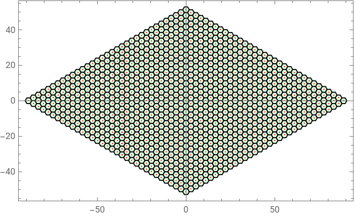
First, the regular hexagon tiling is used to discretize the reflecting mirrors and the target pattern.
In[]:=
hexagon[p_,r_]:=Table[p+r{Cos[θ],Sin[θ]},{θ,0,2Pi-0.1,Pi/3}]
In[]:=
{hexagonCenter2D,hexagonVertice2D}=Module{n=16,r=(3+0.7)/2,b,center},b=r1.5,-
3
2,1.5,3
2;{center=Tuples[Range[-n,n],2].b,Table[hexagon[p,r],{p,center}]};In[]:=
Graphics[{EdgeForm[Black],LightGreen,Polygon/@hexagonVertice2D,Red,AbsolutePointSize[0.05],Point[hexagonCenter2D]},Axes->True,Frame->True]
Out[]=
2.2 Mirror discretization
2.2 Mirror discretization
The first heart-shaped curve defined by an implicit function is used as the boundary of the reflecting mirror.
In[]:=
firstHeartCurve=With{a=18,b=5},ImplicitRegion[(-a≤0)&&y>-22,{x,y}];heartReg=BoundaryDiscretizeRegion[firstHeartCurve,MaxCellMeasure{"Length"0.1},Axes->True,Boxed->True,ImageSize->300]
3
(+-)
2
x
2
(y+b)
2
a
2
x
3
(y+b)
Out[]=
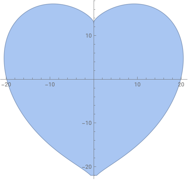
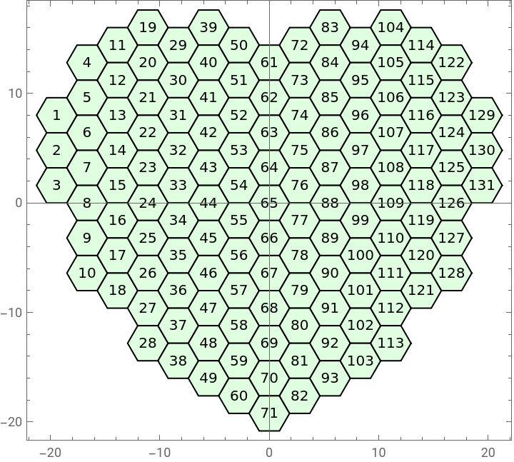
The regular hexagons within the boundary of the heart-shaped curve are selected as sub-mirrors. The number of sub-mirrors can be controlled by adjusting the size of the mirror boundary. In this paper, a total of 131 micro-reflective sub-mirrors are selected.
In[]:=
heartVertice2D=Select[hexagonVertice2D,RegionMember[firstHeartCurve,Mean[#]]&];
In[]:=
mirrorNumber=Length@heartVertice2D
Out[]=
131
Here, a simple column sorting is first performed on the 131 micro sub-mirrors. Subsequently, the pairing relationship between the sub-mirrors and the target pattern area will be further optimized.
In[]:=
heartVerticeSortCol=Sort[heartVertice2D,(Mean[#1][[1]]<Mean[#2][[1]])&];heartVerticeSortT=SplitBy[heartVerticeSortCol,First[Mean[#]]&];heartVerticeSort=Flatten[Sort[#,(Mean[#1][[2]]>Mean[#2][[2]])&]&/@heartVerticeSortT,1];
Visualization processing and mark the numbers at the center of each regular hexagonal sub-mirror.
In[]:=
Graphics[{EdgeForm[Black],LightGreen,Polygon/@heartVerticeSort,Black,Table[Text[Style[i,10],Mean[heartVerticeSort[[i]]]],{i,Length@heartVerticeSort}]},Axes->True,Frame->True]
Out[]=
The following code is designed, purposely. The purpose is to increase the height of the middle reflecting surface and reduce the height of the two side reflecting surfaces, thereby improving the accessibility for the manufacturing process.
In[]:=
pushedVertice=Map[-Abs[(First[Mean[#]])*(If[Abs[(First[Mean[#]])]<=3*2.25,0.05,If[Abs[(First[Mean[#]])]<=4*2.25,0.075,0.09]]/2.25)]&,heartVerticeSort];intersectionVertice3D=Table[Map[N[{#[[1]],pushedVertice[[i]],#[[2]]}]&,heartVerticeSort[[i]]],{i,Length@heartVerticeSort}];
In[]:=
intersectionCenter3D=Mean/@intersectionVertice3D;
In[]:=
Mean[intersectionCenter3D]
Out[]=
{5.42399×,-0.315771,0.660427}
-17
10
3. Light source
3. Light source
3.1 Parallel light
3.1 Parallel light
To simulate the parallel light of the sun and a flashlight (at a long distance), the distance between the flashlight and the reflecting mirror can be adjusted. At a long distance, the light from the flashlight can be approximately regarded as parallel light.
In the code, the mirror array is translated by a certain distance in 3D space, and lines are connecting the corresponding points to obtain parallel light rays.
In[]:=
inputCenter3D=(#+{0,150,150})&/@intersectionCenter3D;
In[]:=
inputRay=Table[{intersectionCenter3D[[i]],inputCenter3D[[i]]},{i,Length@intersectionCenter3D}];
In[]:=
Graphics3D[{EdgeForm[None],Gray,InfinitePlane[{{1,0,-200},{0,1,-200},{0,0,-200}}],Green,Polygon/@intersectionVertice3D,Red,Point[inputCenter3D],Opacity[0.5],Blue,HalfLine/@inputRay},PlotRange->{{-250,250},{-100,400},{-200,200}},Lighting->"Neutral",Axes->True,Boxed->True,AxesLabel->{"x","y","z"}]
Out[]=

In the following text, based on the parallel light here. Taking the known incident parallel light as one of the input condition. At the same time, given the micro-mirrors and the target light spot pattern, the position and orientation (pose) of the micro-mirror array will be solved.
2.2 Point light
2.2 Point light
Similarly, an LED flashlight (at a short distance) can be used to simulate a point light source. By adjusting the distance between the flashlight and the reflecting mirror, the LED flashlight can also be approximately regarded as a point light source.
In[]:=
inputCenter3D={0,100,100};inputRay=Table[{intersectionCenter3D[[i]],inputCenter3D},{i,Length@intersectionCenter3D}];
In[]:=
Graphics3D[{EdgeForm[None],Gray,InfinitePlane[{{1,0,-200},{0,1,-200},{0,0,-200}}],Green,Polygon/@intersectionVertice3D,Red,Point[inputCenter3D],Blue,Opacity[0.9],Line/@inputRay},PlotRange->{{-250,250},{-100,400},{-200,200}},Lighting->"Neutral",Axes->True,Boxed->True,AxesLabel->{"x","y","z"}]
Out[]=

4. Target pattern
4. Target pattern
4.1 Pattern discretization
4.1 Pattern discretization
The three commonly used English characters “I ♥ U” are used as the target pattern, serving as a love secret message presented by the optical reflection jewelry pendant.
Note: Here, in order to achieve a one-to-one pairing between the number of target spots and the number of sub-mirrors, the pattern boundary and size have been carefully adjusted and trimmed so that the number of reflected light spots (131) is exactly equal to the number of sub-mirrors mentioned above (131).
Here, a simple column sorting is also carried out for the 131 target spots.
Currently, the 131 target spots are obtained with marking of order.
4.2 Simple pairing
4.2 Simple pairing
Here, according to the different positions of the three characters of the target spots, we divide the corresponding pairings into three groups.
The three characters in the above figure can correspond to three different color-matching relationships. The pairing of the sub-mirrors of the mirror array and the target light spots is determined by the same numerical numbering. Their position distribution is shown in the following figure.
Later, we will also optimize and explain the pairing relationship between the sub-mirrors of the reflecting mirror and the target pattern area. Here, the corresponding pairing relationship established by this simple sorting is regarded as a result of simple pairing or a random initial state.
5. Ray tracing
5. Ray tracing
5.1 Algorithm steps
5.1 Algorithm steps
The goal of this section is to use the ray tracing algorithm to design a hexagonal planar mirror array that can display arbitrary text and patterns.
1. incident light source
Decide whether it is parallel light or a point light source in space. In this paper, parallel light is chosen.
2. target pattern
Determine the three-dimensional spatial positions of the target pattern and its sub-spots.
3. mirror array
Determine the three-dimensional spatial positions of the micro-mirrors and their sub-mirrors.
4. matching pairs of light rays
Based on a “nearest neighbor principle” and the constrained shortest path optimization algorithm, determine the correspondence between the target light spots and the sub-mirrors.
5. pose of each sub-mirror
5.1 Calculate the normal vector: Based on the incident light ray, the reflected light ray, and the law of reflection, calculate the normal vector of the mirror plane. 5.2 Calculate the plane equation: Using the normal vector of the mirror plane and the intersection point of the reflecting surface and the light ray, calculate the plane equation of the mirror.
5.3 Model the mirror: Based on the plane equation of the mirror and the regular hexagon on the XY plane, calculate the Z coordinate on the plane and project the regular hexagon onto this plane. Generate a three-dimensional model of a hexagonal prism with a reflecting surface based on the upper and lower regular hexagons.
5.2 Pairing problem
5.2 Pairing problem
For the pairing algorithms of the “nearest neighbor principle” related to micro-mirrors array proposed, refer to references [8] - [10]. Among them, Mann et al. [8] proposed that when aligning the field sub-mirror and the pupil sub-mirror, the nearest neighbor principle should be followed. That is, each field sub-mirror should be aligned with the pupil sub-mirror closest to it to reduce the deflection angle of the field sub-mirror. Li et al. [9] proposed a nearest neighbor principle where the entire field mirror surface and the entire pupil mirror surface are divided into upper, middle, and lower three regions. The field sub-mirrors in the central region correspond to the pupil sub-mirrors in the central region, and the field sub-mirrors in the edge regions correspond to the pupil sub-mirrors in the edge regions. Wang et al. [10] proposed that the illumination area of the illumination mode on the pupil plane is axisymmetric. Therefore, the pupil mirror surface is divided into four regions by quadrants, with an equal number of pupil sub-mirrors in each region, and the same for the field mirror surface. They also adopted a flying-eyes matching optimization algorithm based on the artificial bee colony algorithm for optimization.
To further illustrate that the sub-mirror and light-spot pairing problem can be reduced to a specific Traveling Salesman Problem, and for a discussion without loss of generality, a simple example is presented first. As shown in the following figure, there are two planes in 3D space. There are 20 random points in the upper plane, and the random points in the upper plane can be regarded as the center points of the target light spots. Similarly, there are also 20 random points in the lower plane. The number of points in the upper and lower planes is equal, and the random points in the lower plane can be regarded as the center points of the sub-mirrors of the reflecting mirror. A path needs to be found that can connect all the points in the upper and lower planes, and each point can only be passed through once, as shown in the left-hand figure below. Such a problem is a specific type of the Traveling Salesman Problem. Usually, to solve this kind of problem, a penalty-function constraint can be used so that each time the path is optimized, it will search for points in the opposite-side plane, making the red and blue points arranged alternately. For the optimization algorithm of the Traveling Salesman Problem with penalty-function constraints, please refer to reference [11].
As shown in the right-hand figure below, from a top view, the path to be found forms a closed Traveling Salesman Problem path. This problem is somewhat similar to having specified pinholes (to be passed through only once) on two pieces of cloth. The task is to sew these two pieces of cloth together with needle and thread. The question is how to thread the cloth and minimize the total length of the thread used.
Furthermore, divide the shortest path into two parts, as shown in the following figure. Two matching case schemes can be obtained respectively, namely case 1 and case 2. Calculate the lengths of case 1 and case 2 respectively, and select the set with the shortest distance as the final optimized solution. In this way, the global optimal solution to the sub-mirror and light-spot pairing problem can be obtained.
5.3 Optimized pairing
5.3 Optimized pairing
Define the positions of the sub-mirrors and the target-spots in 3D space respectively.
Using an optimization algorithm for the Traveling Salesman Problem with penalty-function constraints. If two points are within the same grouping (in the same plane), a strong penalty function is imposed to force the optimization algorithm to search for points within another grouping as their neighboring points.
For the optimization algorithm calculation, the commonly used “TwoOpt” algorithm (two-edge swap algorithm) is employed to obtain the optimal solution and path.
Two pairing path schemes can be obtained: case 1 and case 2. Calculate the lengths of case 1 and case 2 respectively, and select the set with the shortest distance as the final optimized solution. In this way, the global optimal solution to the sub-mirror and light-spot pairing problem can be obtained.
According to the different positions of the target characters, the corresponding paired light rays are classified by different colors.
Based on the positions of the sub-mirrors of the reflecting mirror, a reflecting mirror model is built simply. The orientation of the reflecting surface of each sub-mirror will be further calculated and determined, subsequently.
5.4 Law of reflection
5.4 Law of reflection
Based on the results of the above optimized pairing, determine the reflected light rays and their unit vectors.
Use the previous definition of parallel light to determine the incident light rays and their unit vectors. According to the law of reflection, under the conditions of known incident light rays and reflected light rays, solve for the orientation of the reflecting surface of the sub-mirror, and find the normal vector of the reflecting surface.
Examine the orientation of the reflecting surface of the sub-mirror based on the normal vector of the reflecting surface, and obtain the histogram of the bias angles of the normal vectors of the sub-mirrors.
5.5 Normal vector of plane
5.5 Normal vector of plane
This subsection is a review section on planes and normal vectors, introducing how to solve for the normal vector based on the plane equation.
5.6 Solving a reflecting plane
5.6 Solving a reflecting plane
In this subsection, the above conclusions are further applied. It introduces how to construct a 3D model of a hexagonal prism with a reflecting mirror based on the plane equation and the normal vector.
5.7 Solving all reflecting planes
5.7 Solving all reflecting planes
In this subsection, the above conclusions are further applied. It introduces how to construct a 3D model of all hexagonal prism with reflecting mirrors based on the plane equation and the normal vector.
Design a function to carry following task. Input is a intersection point and normal, output is to build a hexagonal prism with reflecting mirror.
5.8 Export model
5.8 Export model
The objective of this section is to convert the 3D model constructed above into a regional model and export it as a manufacturing STL format file.
5.9 Complete design
5.9 Complete design
In this section, the 3D model of the micro-mirror array is further refined and then converted into a complete, wearable heart shaped jewelry model.
Stretch the plane of the heart-shaped area to turn it into a 3D region.
Build a torus, then rotate and translate it into specified pose.
6. Simulation
6. Simulation
This article actually discusses beam shaping techniques similar to those in illumination systems. However, for the convenience of explaining the problem, the concept of the depth of focus (DOF) of an objective lens imaging is adopted in this article. To verify the effective depth of focus range of beam imaging, the nominal designed focal plane distance is 250 mm, and the designed depth of focus is ±20 mm. A larger depth of focus is beneficial for the imaging of the optical system and can withstand more external disturbances or optical deviations. Taking this optical jewelry as an example, since the position of the jewelry is manually placed and adjusted by humans, and the distance between the screen and the mirror is also visually estimated and evaluated by humans, there are actually significant deviations between the actual imaging projection distance and the ideal focal length value each time. A larger designed depth of focus is conducive to adapting to such deviations and ensuring that the presented target spot pattern is clear and distortion-free.
6.1 Define function
6.1 Define function
The objective of this section is to design and define some functions for simulation and visualization that can be called later in the text. Three simulation functions have been designed.
1. Geometric simulation
2. Simulation of light intensity outside spots
3. Simulation of light intensity inside spots
In the following content, the intersection point of a line segment and a plane will also be calculated. Therefore, a function for finding the intersection point of a plane and a line is defined. The line is represented by two points, as two points determine a line; the plane is represented by a vector and a point. By simultaneously listing the equations of an arbitrary line and the plane and solving the equations, the intersection point can be obtained. MathWorld : Line-Plane Intersection
6.2 Simple pairing result
6.2 Simple pairing result
The results in this section are based on a simple design of row-column sorting and correspondence for the pairing relationship between the sub-mirror and the target-spots.
Review ordering of the mirror array and the target light spots
In this section, a simple row-column sorting and corresponding design was adopted for the pairing relationship between the sub-mirrors of the reflecting mirror and the target spots. In terms of the content discussed, what this article explores is essentially similar to the beam shaping technology of illumination systems. However, to explain relevant issues more clearly, the concept of the depth of focus of objective lens imaging was introduced. In order to verify the effective depth of focus range of beam imaging, the nominal designed focal plane distance is set to 250 mm. Meanwhile, the distances of 230 mm and 270 mm are defined as the limit distances of the depth of focus. The verification results through simulations show that at these two limit distances of 230 mm and 270 mm, there will be an offset of one light spot diameter. Considering the actual situation comprehensively, this offset is regarded as the maximum acceptable range.
6.3 Optimized pairing result
6.3 Optimized pairing result
In this section, the pairing relationship between the sub-mirrors and the target spots is calculated using a constrained shortest path optimization algorithm.
Given the six vertices of a reflecting mirror and the emerging rays from the mirror, that is, the rays emerging from these vertices are known, find the intersection points of these lines with an arbitrary plane.
In this section, the pairing relationship between the sub-mirrors and the target spots is designed based on a constrained shortest path optimization algorithm. Similarly, to verify the effective depth of focus range of beam imaging, the nominal designed focal plane distance in this paper is 250 mm. The distances of 230 mm and 270 mm are regarded as the limit distances of the depth of focus. Through simulation calculations, it can be seen that at 230 mm and 270 mm, there is only an offset of 1/4 to 1/3 of a light spot diameter. The change in the light spot position is very small, and the improvement effect is obvious. If an offset of one light spot diameter is used as the standard, the effective distance of the depth of focus is expected to be increased by 3 to 4 times. A larger depth of focus is beneficial for the imaging of the optical system and can withstand more disturbances or optical deviations. Taking this optical jewelry as an example, since the position of the jewelry is manually placed and adjusted by humans, and the distance between the screen and the reflecting mirror is also visually estimated and evaluated by humans, there are actually significant deviations between the actual projection distance of imaging and the ideal focal length value each time. Designing a larger depth of focus is conducive to adapting to such deviations and ensuring that the presented target light spot pattern is clear and distortion-free.
7. Rendering
7. Rendering
7.1 Front view
7.1 Front view
7.2 Back view
7.2 Back view
8. Manufacture
8. Manufacture
For the manufacturing of a micro mirror array with ultra-high precision, predecessors have attempted various methods. They used a 248 nm KrF excimer laser, a 5- axis high-speed milling machine, a high-speed CNC machining center, or a precision carving device for milling and processing to create micro-nano structures. The ways of manufacturing micro-nano structures are diverse, as referenced in [12][13].
In the visible light spectrum, the wavelength ranges of different colors are as follows: red light is in the range of 640 - 780 nm, orange light is 640 - 610 nm, yellow light is 610 - 530 nm, green light is 505 - 525 nm, blue light is 505 - 470 nm, and violet light is 470 - 380 nm. Therefore, the maximum depth of the micro-structure can be less than approximately 380 nm. Since the smaller the size, the greater the processing difficulty, a maximum depth of 400 nm for the micro-structure can balance both processing accuracy and reflection effect.
In this paper, to achieve a better reflection effect, the surface form accuracy of the metal surface reaches a level superior to λ/20, that is, RMS (Root Mean Square) is 18 nm and Ra (Arithmetic Average Roughness) is 13 nm. The surface roughness instrument of Zygo Corporation in the United States is used for detection.
In this paper, to achieve a better reflection effect, the surface form accuracy of the metal surface reaches a level superior to λ/20, that is, RMS (Root Mean Square) is 18 nm and Ra (Arithmetic Average Roughness) is 13 nm. The surface roughness instrument of Zygo Corporation in the United States is used for detection.
9. Prototype
9. Prototype
To test and verify the effectiveness of the micro-mirror array imaging, a testing scheme under visible light conditions is adopted as follows.
In a dark field environment, the actual effect of reflecting light onto a white wall is achieved by illuminating with a flashlight. As shown in the following photo, each sub-light spot is clearly visible, and it has a high degree of consistency with the expected simulation results. Note: There is a missing light spot at the lower-right corner of the heart shape. This is because several local sub-mirrors were not processed properly during the mentioned manufacturing process.
The wearing the optical jewelry in this paper is shown in the following figure.
It was tested and verified under sunlight during the day. The effect projected onto a white wall is shown in the video below. During the day-time sunlight, the position of the sun is uncontrollable, and a reflection angle can be approximately estimated. The orientation of the projection screen usually cannot be changed either. Since the position of the jewelry is manually placed and adjusted by humans, and the distance between the screen and the reflecting mirror is also visually estimated and evaluated by humans, all these factors will generate bias and deviations between theoretical assumptions and real world. It can be seen that designing a larger depth of focus is beneficial for adapting to various deviations and ensuring that the presented target light spot pattern is clear and distortion-free.
10. Review
10. Review
◼
Building a ray-tracing model of mirror array for arbitrary pattern;
◼
Resolving nearest pairing problem based on constrained finding-shortest-tour method;
◼
High-precision manufactured micro-mirror array for heart shape pendant;
◼
Design a necklace-pendant with double-sides pattern;
◼
Simulating and comparing the result of depth-of-focus (DOF).
11. Acknowledgments
11. Acknowledgments
12. Summary
12. Summary
In the past decade, the boundaries between technology and art are gradually blurring and disappearing. An advanced technological product can also be regarded as an amazing work of art. A great work of art is often the reflection of technological advancements. A customized piece of jewelry can be worn by an individual to convey love, while an article may reach thousands of readers, inspiring even more creativity.
13. Reference
13. Reference
[1] Marios Papas, et al. Goal-based Caustics, Eurographics, Vol. 30 (2), 2011
[2] Yonghao Yue, et al. Poisson-Based Continuous Surface Generation for Goal-Based Caustics, ACM Transactions on Graphics, 2014
[3] Yuliy Schwartzburg, et al. High-contrast Computational Caustic Design, ACM Transactions on Graphics, 2014
[5] Yuanping Song, et al. A review of micro-mirror arrays, Precision Engineering, 2018
[6] Cai Hanrong, A Metal Surface for Reflective Projection Imaging and Its Processing Method, CN202011476877[P], 2022
[7] The Rayy, homepage, https://therayy.com/
[8] Mann H. J, Singer W, Schultz J, et al. Illumination system particularly for microlithography, US7456408[P], 2008
[9] Li Yanqiu, Mei Qiuli, Liu Fei, Extreme Ultraviolet Lithography Fly- Eye Light - Homogenizing Off - Axis Illumination System and Method for Realizing Off - Axis Illumination CN103092000A[P], 2022
[10] Wang Xin, Li Zhongliang, Yuan Chunxiao. Research on Pupil Shaping Technology of Extreme Ultraviolet Lithography Illumination System[J]. Chinese Journal of Lasers Vol. 51 (12), 2024
[11] Wu Fei, Selection of Mathematica Demonstrations Projection, Tsinghua University Press 2010
[12] Yoshinori Hashimoto, .et al., Manufacture of fly-eye mirror in extreme ultraviolet lithography illumination system by means of ultraprecision diamond cutting, SPIE Vol. 4688, 2002
[13] Yoshinori Hashimoto, .et al., Ultraprecision 5-Axis Control Machining of Fly-eyes Mirror in EUV Lithography, JSME International Journal, 2004
CITE THIS NOTEBOOK
CITE THIS NOTEBOOK
Love heart jewelry V: Optical Secret
by Frederick Wu
Wolfram Community, STAFF PICKS, February 3, 2025
https://community.wolfram.com/groups/-/m/t/3376909
by Frederick Wu
Wolfram Community, STAFF PICKS, February 3, 2025
https://community.wolfram.com/groups/-/m/t/3376909