ABSTRACT (original article): Scalable optical wireless networks are crucial to address the demand for ultra-broadband wireless connectivity in future workspaces and living environments. This study presents a novel theoretical framework for the dual-carrier modular optical phased array (MOPA) architecture, specifically tailored for indoor wireless communication networks. We introduce the non-uniform spherical wave (NUSW) model for a near-field analysis of electromagnetic radiation in a single-carrier MOPA, extending this to dual-carrier configurations. Our analysis demonstrates enhanced beam-focusing capabilities and significant suppression of grating lobes in the dual-carrier system. Expanding on this theoretical model, we perform a comprehensive numerical analysis of a dual-carrier MOPA system installed on a planar ceiling within an indoor room. To quantitatively assess grating lobe suppression, we propose a novel figure-of-merit (FoM) and compare the beam-focusing performance of both single-and dual-carrier MOPA systems. Furthermore, we introduce a new symmetrical excitation mechanism combined with spatial modulation for data symbol encoding within the MOPA architecture. Our results reveal that this approach provides high-level physical layer security (PLS) for wireless communication. By integrating amplitude shift keying (ASK) with spatial modulation, we evaluate the bit error rate (BER) against signal-to-noise (SNR) ratio across different symmetrical excitation scenarios. This evaluation demonstrates that our system achieves efficient digital signal communication with reduced complexity and robust performance under real-world noise conditions. Our findings advance the understanding of optical phased array systems and underscore their potential for secure, high-performance indoor wireless communication. CITATION (original article): Kosala Herath, Malin Premaratne, Sharadi Gunathilake, and Ampalavanapillai Nirmalathas (2024), Symmetrical Modular Optical Phased Array with Integrated Spatial and Frequency Modulation for Scalable Indoor Wireless Communication, IEEE Open Journal of the Communications Society, vol. 5, pp. 7317-7340. https://doi.org/10.1109/OJCOMS.2024.3496866
Keywords: Indoor wireless networks, Modular optical phased array (MOPA), Near-field modelling, Non-uniform spherical wave (NUSW), Beam-focusing pattern, Gating lobes, Spatial modulation
Introduction
Introduction
This notebook demonstrates how a modular architecture can enhance beam-steering performance and reduce grating lobes in phased arrays operating at optical frequencies. Traditionally, phased array-based wireless communication systems have been implemented in the radio frequency (RF) range, and more recently, in the millimeter-wave range. However, as we transition to higher frequency regimes to support higher data transfer rates, phased array design becomes increasingly complex due to system miniaturization. This complexity has limited the use of such systems in indoor wireless communication scenarios. The introduction of modular architecture offers a scalable and achievable solution to these challenges. However, one drawback of modular architectures is the introduction of additional grating lobes compared to conventional phased array designs. To address this, we propose a novel dual-carrier signal transmission method, which dynamically suppresses these grating lobes. Furthermore, we present an integrated modulation approach that combines spatial and frequency modulation techniques, enabling improved wireless communication performance in indoor environments.
In this analysis, we begin by comparing the electric field radiation patterns and the corresponding beam-focusing patterns of single-carrier MOPA and dual-carrier Higher wavelength option (MOPA) configurations, where the elements are positioned arbitrarily in 3D space. These two configurations are illustrated in Figure 1.
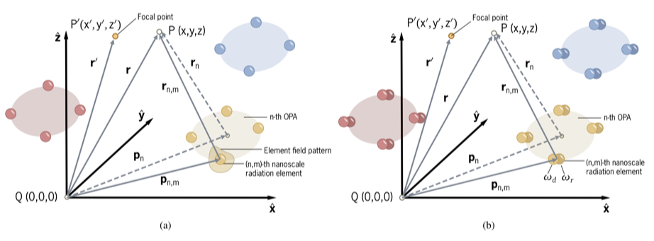
FIGURE 1: The system comprises a MOPA in 3D space with two different configuration:(a) single-carrier emitters and (b) dual-carrier emitters.
In the second phase, we analyze the impact of using a symmetrical excitation mechanism on the beam-focusing pattern. Following this, we evaluate the system’s performance under varying noise levels and multipath effects, providing a comprehensive understanding of its robustness in diverse operating conditions.
Import Libraries and Define Style Parameters
Import Libraries and Define Style Parameters
In[]:=
ClearAll["Global`*"](*Clearvariablesandmemory*)
Import External Libraries:
Import External Libraries:
In[]:=
Needs["MaTeX`"];(*Touselatex*)Needs["SciDraw`"];(*Todrawplots*)
Define plot parameters.
In[]:=
SetOptions[LogTicks,MajorTickLength->{0.03,0},MinorTickLength->{0.013,0}];(*Defineticksizesinlofplots*)SetOptions[LinTicks,MajorTickLength->{0.025,0},MinorTickLength->{0.015,0}];(*Defineticksizesinlineplots*)
Define Colors:
Define Colors:
Define colors for plots and graphs.
In[]:=
Color1=RGBColor[0,0.121,0.317];Color2=RGBColor[0,0.419,0.560];Color3=RGBColor[0.023,0.533,0.607];Color4=RGBColor[0.90,0.631,0.243];Color5=RGBColor[0.996,0.423,0.192];Color6=RGBColor[0.8,0.160,0.211];Color7=RGBColor[0.031,0.254,0.360];Color8=RGBColor[0.92,0.92,0.92];
Define colors and color function for contour plots.
In[]:=
Color9=RGBColor[20/255,90/255,147/255];Color10=RGBColor[52/255,124/255,184/255];Color11=RGBColor[110/255,172/255,209/255];Color12=RGBColor[178/255,213/255,231/255];Color13=RGBColor[228/255,238/255,244/255];Color14=RGBColor[251/255,233/255,223/255];Color15=RGBColor[250/255,192/255,164/255];Color16=RGBColor[230/255,131/255,103/255];Color17=RGBColor[196/255,65/255,60/255];fieldColorFunction=Function[{z},Which[z<=0.0125,Color9,z<=0.025,Color10,z<=0.0375,Color11,z<=0.05,Color12,z<=0.0625,Color13,z<=0.075,Color14,z<=0.0875,Color15,z<=0.1,Color16,True,Color17]];
Define System Parameters:
Define System Parameters:
For the numerical analysis, we consider an indoor room with the dual-carrier MOPA system installed on the ceiling as shown in Figure 2 (a). Consequently, all emitters and modules are positioned in a 2D plane parallel to the room floor. This setup is depicted in Figure 2 (b), illustrates how the MOPA is configured within an indoor room with modules and emitters in a simple square lattice arrangement. We assume that each module is equidistant from adjacent modules within the MOPA, and each nanoscale emitter is also positioned at an equal distance from adjacent elements.
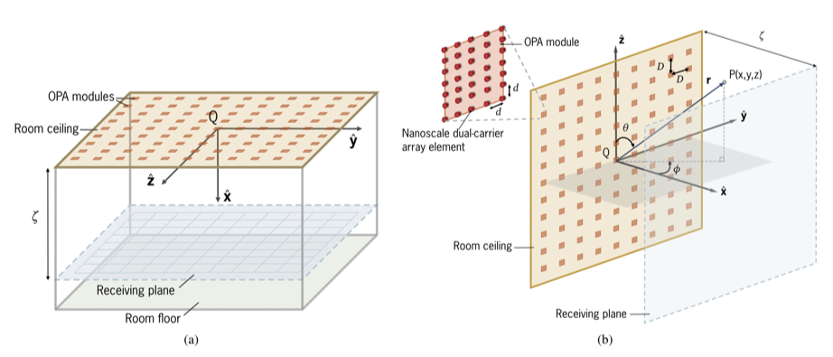
FIGURE 2: (a) The MOPA architecture-based optical wireless communication system implemented for an indoor room with a square lattice arrangement. The OPA modules are mounted on the ceiling, and the data receiving plane is assumed to be parallel to the floor, at a distance ζ from the ceiling. (b) The MOPA system with an arbitrary observation point P in three-dimensional space is depicted here.
We utilize the system’s operating and implementation parameters as outlined in Table 1 to ensure consistency and accuracy in our analysis and simulations.
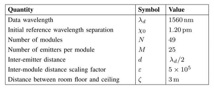
TABLE 1: Operational and physical parameters with their selected values in SI units.
Physical Constants:
Physical Constants:
In[]:=
c=Quantity[(2.997924)*10^(8),"Meters"/"Seconds"];(*speedoflightinvacuum*)ϵ0=Quantity[(8.854187)*10^(-12),("Coulombs"^2*"Seconds"^2)/("Kilograms"*"Meters"^(3))];(*vacuumpermittivity*)
System Operating Parameters:
System Operating Parameters:
Given that our system operates in the optical range, and most beam-steering systems utilize optical waves within the near-infrared (NIR) region—known for their non-penetrative nature to the human eye—we assume that our proposed MOPA architecture employs NIR frequency signals to transmit data. This choice aligns with the safety and performance requirements of the application. Thus, we set the data transmission wavelength ) to 1560 nm, a standard within the near-infrared (NIR) region, aligning with the operational requirements of our proposed MOPA architecture. Furthermore, we introduce the reference wavelength separation parameter (χ) to define the wavelength difference between the dual-carrier signals. This parameter plays a crucial role in analyzing and optimizing the performance of the dual-carrier MOPA system.
(
λ
d
In[]:=
λ
d
χ
0
System Implementation Parameters:
System Implementation Parameters:
For this analysis, to simplify the representation and facilitate analytical discussions, we assume that the indoor environment is a symmetrical, square-shaped room.
In[]:=
N
0
M
0
d
0
λ
d
5
10
Additional Parameter Calculations:
Additional Parameter Calculations:
Calculation of additional parameters required for numerical analysis using the defined system parameters. Here, we consider two effective wavelengths
In[]:=
λ
r
λ
d
λ
eH
λ
d
λ
r
2(-)
λ
d
λ
r
λ
eL
λ
d
λ
r
2(-)*4
λ
d
λ
r
D
0
d
0
λ
r
λ
d
Choose between a high or low effective wavelength for the numerical analysis results.
MOPA Beam-Focusing Pattern Comparison (Single vs Dual)
MOPA Beam-Focusing Pattern Comparison (Single vs Dual)
Functions Related to Beam-Focusing Patterns:
Functions Related to Beam-Focusing Patterns:
This function calculates the Euclidean distance between the center point and a given emitter in the MOPA system within a 3D Cartesian coordinate system.
These three functions calculate the beam-focusing patterns for both single-carrier and dual-carrier systems.
Single-Carrier Beam Focusing Pattern:
Dual-Carrier Beam Focusing Pattern:
To illustrate the effects of the introduced envelope factor, we depict the envelope factor separately. This function defines the envelope factor in the dual-carrier method.
Envelope Factor Pattern:
Generation of Plots - Changing the Focal Point and Effective Wavelength (Figure 3 in Article):
Generation of Plots - Changing the Focal Point and Effective Wavelength (Figure 3 in Article):
Populate z-axis data points for plots.
Please select ‘High Effective Wavelength’ as the effective wavelength. Compute the normalized electric field values for specified z-axis points for single-carrier, dual-carrier, and envelope beam-focusing patterns (Note: Due to the large number of points, this process may take some time).
Create a figure for the generated plot using the ‘SciDraw’ package.
Please select ‘Low Effective Wavelength’ as the effective wavelength. Compute the normalized electric field values for specified z-axis points for single-carrier, dual-carrier, and envelope beam-focusing patterns (Note: Due to the large number of points, this process may take some time).
Create a figure for the generated plot using the ‘SciDraw’ package.
Generation of Plots - Changing the Number of Total Modules (Figure 4 in Article):
Generation of Plots - Changing the Number of Total Modules (Figure 4 in Article):
Define the number of modules in the MOPA configuration.
Please select ‘Low Effective Wavelength’ as the effective wavelength. Compute the normalized electric field values for specified z-axis points for single-carrier, dual-carrier, and envelope beam-focusing patterns (Note: Due to the large number of points, this process may take some time).
Create a figure for the generated plot using the ‘SciDraw’ package.
Generation of Plots - Changing the Configuration of Modules (Figure 5 in Article):
Generation of Plots - Changing the Configuration of Modules (Figure 5 in Article):
Define the number of modules in the MOPA configuration.
Specify the beam-focusing patterns for single-carrier and dual-carrier systems based on the module configurations: “Square”.
Please select ‘Low Effective Wavelength’ as the effective wavelength. Compute the normalized electric field values for specified z-axis points for single-carrier, dual-carrier, and envelope beam-focusing patterns (Note: Due to the large number of points, this process may take some time).
Define the number of modules in the MOPA configuration.
Specify the beam-focusing patterns for single-carrier and dual-carrier systems based on the module configurations: “Rectangular-Shaped: z-axis”.
Please select ‘Low Effective Wavelength’ as the effective wavelength. Compute the normalized electric field values for specified z-axis points for single-carrier, dual-carrier, and envelope beam-focusing patterns (Note: Due to the large number of points, this process may take some time).
Define the number of modules in the MOPA configuration.
Specify the beam-focusing patterns for single-carrier and dual-carrier systems based on the module configurations: “Rectangular-Shaped: y-axis”.
Please select ‘Low Effective Wavelength’ as the effective wavelength. Compute the normalized electric field values for specified z-axis points for single-carrier, dual-carrier, and envelope beam-focusing patterns (Note: Due to the large number of points, this process may take some time).
Symmetrical Excitation-based MOPA Beam-Focusing Pattern Comparison (Single vs Dual)
Symmetrical Excitation-based MOPA Beam-Focusing Pattern Comparison (Single vs Dual)
In the previous section, we considered the excitation of all modules placed on room’s ceiling. However, we now introduce a novel symmetrical excitation of modules based on the focal point as illustrated in Figure 6.
FIGURE 6: The grid configuration on the receiving plane is a projection of the square lattice generated by the dual-carrier MOPA implementation on the ceiling. Here, the focal point lies within the focal region, and the projection of this focal region is displayed on the ceiling. (b) The symmetrical excitation of modules around the focal region, as viewed from the receiving plane, is illustrated using two distinct excitation levels: the inner circle and outer circles.
Generation of Plots - Changing Symmetrical Excitation Mode and Axis (Figure 7 in Article):
Generation of Plots - Changing Symmetrical Excitation Mode and Axis (Figure 7 in Article):
These numerical calculations are conducted to demonstrate the beam-focusing pattern and the electric field intensity differences between the inner and outer circles, based on the symmetrical excitation of the MOPA architecture along two axes in the receiving plane.
Please select ‘Low Effective Wavelength’ as the effective wavelength. Compute the normalized electric field values for specified y-axis points for single-carrier, dual-carrier, and envelope beam-focusing patterns (Note: Due to the large number of points, this process may take some time).
Please select ‘Low Effective Wavelength’ as the effective wavelength. Compute the normalized electric field values for specified y-axis points for single-carrier, dual-carrier, and envelope beam-focusing patterns (Note: Due to the large number of points, this process may take some time).
Please select ‘Low Effective Wavelength’ as the effective wavelength. Compute the normalized electric field values for specified z-axis points for single-carrier, dual-carrier, and envelope beam-focusing patterns (Note: Due to the large number of points, this process may take some time).
Please select ‘Low Effective Wavelength’ as the effective wavelength. Compute the normalized electric field values for specified z-axis points for single-carrier, dual-carrier, and envelope beam-focusing patterns (Note: Due to the large number of points, this process may take some time).
Generation of Plots - Changing Symmetrical Excitation Mode for Contour Plots (Figure 8 in Article):
Generation of Plots - Changing Symmetrical Excitation Mode for Contour Plots (Figure 8 in Article):
Wireless Communication Performance Analysis: Noise Effects
Wireless Communication Performance Analysis: Noise Effects
BER vs SNR for Three Different Scenarios (Figure 9 in Article):
BER vs SNR for Three Different Scenarios (Figure 9 in Article):
Define custom plot marker function.
Generate figure of BER vs SNR to evaluate the performance against noise effects.
Wireless Communication Performance Analysis: Multi-Path (MP) Effects
Wireless Communication Performance Analysis: Multi-Path (MP) Effects
For this analysis, we focus solely on Scenario 3 and incorporate the effects of multi-path propagation to demonstrate how the system behaves under such conditions. For this we define the parameters related to Scenario 3.
Define Rice Distribution:
Define Rice Distribution:
We utilize the Rice distribution to model the multi-path effects within our system framework. Here, K is the Rice factor.
Choose Rice factor (in dB) for the calculations.
Compute the BER values for the specified SNR levels under the selected multi-path effect strength.
BER vs SNR for Different Rice Factors (Figure 10 in Article):
BER vs SNR for Different Rice Factors (Figure 10 in Article):
Create a figure to compare BER values with and without multi-path effects for a specified Rice factor.
Acknowledgement
Acknowledgement
This work was supported by the Australian Research Council (ARC) through the Discovery Project under Grant DP230101757.
CITE THIS NOTEBOOK
CITE THIS NOTEBOOK
Scalable indoor wireless networks: symmetrical modular optical phased array w/ combined modulation
by Kosala Herath, Malin Premaratne, Sharadhi Gunathilake & Ampalavanapillai Nirmalathas
Wolfram Community, STAFF PICKS, December 11, 2024
https://community.wolfram.com/groups/-/m/t/3338291
by Kosala Herath, Malin Premaratne, Sharadhi Gunathilake & Ampalavanapillai Nirmalathas
Wolfram Community, STAFF PICKS, December 11, 2024
https://community.wolfram.com/groups/-/m/t/3338291