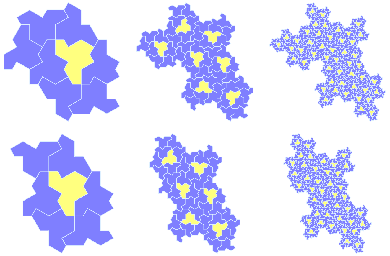
From many discussions before, the fastest way to tile with hat tiles is by substitution rule. The original paper gives two groups of super-tiles generated by substitution. One is HTPF super-tiles. The other one is H7 super-tile, which has a fractal recursive structure. How to build large hat tile cluster to cover the infinite plane via HTPF equivalence has been implemented in Mathematica by Brad Klee, while there is another website created by one of the authors can draw HTPF super-tiles. In this memo, we want to generate H7 super-tile by substitution rule, to reproduce and reprove the process shown in Figure 2.11 of the original paper. A special feature of this H7 substitution rule is, it is a fractal substitution.
Hat tile and H2
Hat tile and H2
To depict the hat tile, we use the same idea by Brad Klee, which is walking along a certain sequence of angles and distance, namely vectors, to obtain the boundary of the hat tile polygon. And here we continue to use general code for hat tile family given in a previous discussion.
In[]:=
TileVertices[step_][or_,dir_,ref_,pt_] := With[basicVertices = AnglePath[ {step[[2]], -Pi/6+dir*Pi/6},{step[[2]], Pi/3},{step[[1]], Pi/2},{step[[1]], Pi/3}, {step[[2]], -Pi/2},{step[[2]], Pi/3},{step[[1]], Pi/2},{step[[1]], -Pi/3},{step[[2]], Pi/2}, {step[[2]], -Pi/3},{step[[1]], Pi/2},{step[[1]], Pi/3},{step[[1]], 0} ], Expand[# + or&/@(If[ref,{-#[[1]],#[[2]]},#]&/@((#-basicVertices[[pt]])&/@basicVertices))]]
In[]:=
Tile[step_][or_,dir_,ref_,pt_] := Polygon[TileVertices[step][or,dir,ref,pt]]
The code above can give the family of aperiodic tiles in the original paper denoted as Tile(n,m) where list {n,m} makes up to argument step.
Particularly, the hat tile is Tile(1,).
Particularly, the hat tile is Tile(1,
3
In[]:=
hatVertices:=TileVertices[{1,Sqrt[3]}];hat:=Tile[{1,Sqrt[3]}];
In the original paper, the author merges a reflected tile and a neighbor unreflected one to get a tile named “H2”. And we name one single hat tile “H1”. They are:
Out[]=
H2 | H1 |
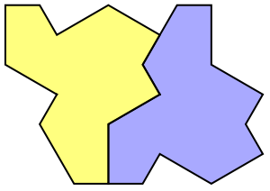
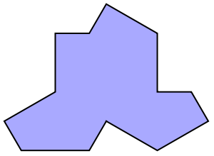
Where the blue tile is unreflected while yellow is reflected. And H2 is forced to grow to H7 and H8, which can be derived by the vertex configuration discussed before. Here are they:
Out[]=
H7 | H8 |
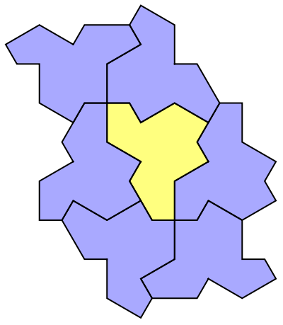
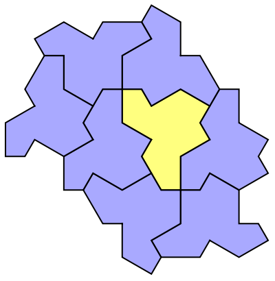
Then, the author use the substitution rule to get H7-super-tile in a way that replace each H2 with H7 and replace each H1 with H8. And its super-tile is like:
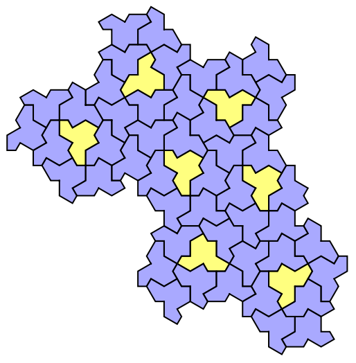
Now, we begin to construct this kind of amazing fractal super-tile:
Brief Analysis
Brief Analysis
In fact, if we merge H2 and regard it as one single tile, there are 7 tiles (six H1 and one H2) in H8, which corresponds to that super-tile consists of six H8 and one H7, exactly 7 tiles. So, the substitution can be start with H1 and H2 rather than H7 and H8.
The original paper does not give the substitution rule for this process. So we need to explore by ourselves.
From the Figure 2.11 we can read there are some important points indicating how these super-tile connect to each other. We call them “control points”. From the figure we can find out the rule from H7 and H8 to super-tile by observation, and from H2 and H1 to H7 and H8, by observation and try.
The following is the information for H1, H2, H7 and H8:
The following is the information for H1, H2, H7 and H8:
In[]:=
H2Tile=<|"controlPoints"->,"code"->|>;H1Tile=<|"controlPoints"->,"code"->|>;H7Tile=<|"controlPoints"->,"code"->|>;H8Tile=<|"controlPoints"->,"code"->|>;
And a function to visualize:
In[]:=
Options[depictControlPoints]=Join[Options[Graphics],Options[Show]];depictControlPoints[tile_,opt:OptionsPattern[]]:=Show[ Graphics[tile["code"]/.{pos_,or_,False,v_}:>{Opacity[.5],EdgeForm[Black],Lighter@Blue,Tile[{1,Sqrt[3]}][pos,or,False,v]}, {pos_,or_,True,v_}:>{Opacity[.5],EdgeForm[Black],Yellow,Tile[{1,Sqrt[3]}][pos,or,True,v]}],Graphics[{Red,PointSize[.03],Point[tile["controlPoints"]],Line[Partition[tile["controlPoints"],2,1,1]]}],opt];
The following are these four clusters and their control points:
Out[]=
| ||||
|
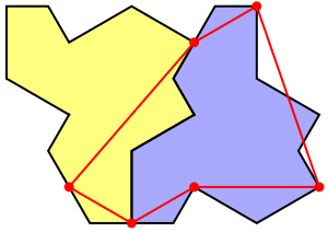
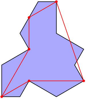
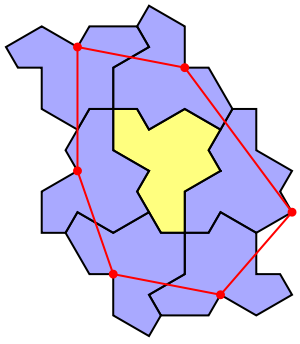
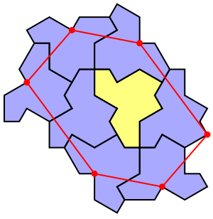
What substitution does is replace each part of the cluster by corresponding super-cluster, and update control points by some calculations.
First we need functions to translate and rotate a cluster, and place a cluster at a given position with given rotation angle.
First we need functions to translate and rotate a cluster, and place a cluster at a given position with given rotation angle.
In[]:=
rotateCluster[code_,r_]:=Replace[code,{{pos_,dir_,False,pt_}:>{RotationMatrix[r*Pi/6].pos,Mod[dir+r,12],False,pt},{pos_,dir_,True,pt_}:>{RotationMatrix[r*Pi/6].pos,Mod[dir-r,12],True,pt}},{1}];translateCluster[code_,vec_]:={#1+vec,#2,#3,#4}&@@@code;placeCluster[pos_,dir_,code_]:=translateCluster[rotateCluster[code,dir],pos];
Then, a function to do substitution calculation is implemented:
In[]:=
substitute[tile1_,tile2_]:=Module[{T1=placeCluster[tile1["controlPoints"][[1]],0,tile1["code"]],T2=placeCluster[tile1["controlPoints"][[4]],0,tile2["code"]],T3,T4,T5,T6,T7},T3=placeCluster[tile1["controlPoints"][[6]],4,tile2["code"]];T4=placeCluster[tile1["controlPoints"][[5]],2,tile2["code"]];T5=placeCluster[tile1["controlPoints"][[4]]+tile2["controlPoints"][[2]],8,tile2["code"]];T6=placeCluster[tile1["controlPoints"][[4]]+tile2["controlPoints"][[3]],10,tile2["code"]];T7=placeCluster[tile1["controlPoints"][[4]]+tile2["controlPoints"][[4]],0,tile2["code"]];With[{newPt=tile2["controlPoints"][[4]]},<|"tile1"-><|"code"->Join@@{T1,T2,T3,T4,T5,T6},"controlPoints"->{tile1["controlPoints"][[1]],RotationMatrix[8Pi/6].newPt+tile1["controlPoints"][[4]]+tile2["controlPoints"][[2]],RotationMatrix[10Pi/6].newPt+tile1["controlPoints"][[4]]+tile2["controlPoints"][[3]],newPt+tile1["controlPoints"][[4]],RotationMatrix[2Pi/6].newPt+tile1["controlPoints"][[5]],RotationMatrix[4Pi/6].newPt+tile1["controlPoints"][[6]]}|>,"tile2"-><|"code"->Join@@{T1,T2,T3,T4,T5,T6,T7},"controlPoints"->{tile1["controlPoints"][[1]],RotationMatrix[8Pi/6].newPt+tile1["controlPoints"][[4]]+tile2["controlPoints"][[2]],RotationMatrix[10Pi/6].newPt+tile1["controlPoints"][[4]]+tile2["controlPoints"][[3]],newPt+tile1["controlPoints"][[4]]+tile2["controlPoints"][[4]],RotationMatrix[2Pi/6].newPt+tile1["controlPoints"][[5]],RotationMatrix[4Pi/6].newPt+tile1["controlPoints"][[6]]}|>|>]]
Now we use substitution rule to generate super-tile, super-super-tile and so on.
More than that, we can obtain much higher level of super-tile:
Here are more details about how control points are chosen:
From H7,H8 to Super-tile
From H7,H8 to Super-tile
Let start with H7 and H8, which is exactly how the original paper starts.
Let us draw a super-tile to see what these red point and lines mean:
These points indicate how neighbor clusters connect to the two in the center. It is easier to see in the original paper:
The red points are some control points used to construct the cluster. We can fix the first control point of cluster “1”at original point, then use three control points on it to get “2”, “3”, “4”. Then use three control points on cluster “2” to get “5”, “6”, “7”. For the convenience and elegance, the control points I record are redundant. Since you can see there are only three of H7 and three of H8 are used.
And the new control points of this super tile is:
And the new control points of this super tile is:
There rule is, the new control points are all on the “last” hat tile of the H8, the tile H8 has while H7 does not, and control points are always point 1, which is at the “bottom” of the hat tile. (Except the control point in the middle and on the right, which is fixed actually, and regarded as original point here.)
There is another “H7” super-tile, (above one is “H8” super-tile).
There is another “H7” super-tile, (above one is “H8” super-tile).
This one is used as a replacement of H7 in the future substitution. Observe the following figure from the original paper:
The right one in the red circle is H7 super-tile and the right one is H8 super-tile.
Then we use the idea discussed above to generate the super-super-tile:
Then we use the idea discussed above to generate the super-super-tile:
You can nest map the function to get higher-level super-tiles and the whole process:
From H2, H1
From H2, H1
It’s inelegant if we need to construct fractal cluster from H7 and H8, which are regarded as meta-tiles in the original paper. Since if we regard H2 as an inferior tile of H7 and one single tile as that of H8, we can get control points by observation, as well as many tries actually.
Here are the control points I find:
From these control points configurations, we can generate H7 and H8 with the same idea and rule before:
So, we can get H2 and H1 into this big fractal family. However, it is non-sense to replace nothing into tiles, which is what we do from H2 to H7, and H1 to H8. But, at least we find a way to do fractal substitution from one or two tiles, which are more natural and elegant.
Reference
Reference
◼
Hat tilings via HTPF equivalence by Brad Klee. Wolfram Community MAR 24 2023.
◼
Hat combinatorics: the ten vertex theorem by Brad Klee. Wolfram Community, STAFF PICKS, June 12 2023
◼
Hat tiling space reduction and grow function implementation by Bowen Ping. Wolfram Community, STAFF PICKS, July 11, 2023
◼
Hat tiling: vertex configurations further reduction by Bowen Ping. Wolfram Community, STAFF PICKS, July 14, 2023
Acknowledgement
Acknowledgement
Thanks to Brad Klee for his guide during WSS23, which inspired me to explore such amazing tiling problem!
CITE THIS NOTEBOOK
CITE THIS NOTEBOOK
Hat tiling: fractal substitution
by Bowen Ping
Wolfram Community, STAFF PICKS, July 29, 2023
https://community.wolfram.com/groups/-/m/t/2979005
by Bowen Ping
Wolfram Community, STAFF PICKS, July 29, 2023
https://community.wolfram.com/groups/-/m/t/2979005