A powerful boxing cross is produced not by the arm alone but through a proximal-to-distal kinetic chain. The legs drive the pelvis, and rotational momentum is transferred through the trunk to the fist. My study develops a reduced-order model of that chain, in which two rigid segments, pelvis and shoulders, rotate about a longitudinal axis. The two segments are coupled by a joint torque that combines passive viscoelastic resistance with an active Hill-type muscular contribution. Simulations identify the hip–shoulder separation as the key mechanism that transfers momentum toward the fist, and the model is compared against filmed punches. The result is a simple, physically interpretable framework for punching technique, motivated by my interest in its applications to biomechanics and humanoid robotics. Future work will extend the two-segment chain toward the distal arm and impact dynamics.
Introduction
Introduction
The Human Punch as a Kinetic Chain
The Human Punch as a Kinetic Chain
A boxing cross looks like an act of the arm. However, mechanically, it is the result of a proximal-to-distal kinetic chain. The chain starts with the legs first driving the pelvis. Rotation is then carried through the trunk into the shoulders, and finally, momentum is transferred to the fist. The chain works because the pelvis rotates ahead of the shoulders. This delay is known as the hip–shoulder separation. It is the mechanism this computational essay places at its centre.
Force Transmission
Force Transmission
The coupling between the lower and upper trunk behaves like a loaded spring. As the pelvis leads, the potential energy in the connective tissue across the two segments, increases. Elastic energy is stored and later released to accelerate the shoulders. I model this with a joint torque by combining a passive viscoelastic term (torsional stiffness and damping) with an active Hill-type muscular contribution, and track the mechanical power transmitted through the core joint. The model is made up of two rigid segments rotating about a shared axis and joined by a torque-producing coupling.
Motivation from Robotics and Multibody Dynamics
Motivation from Robotics and Multibody Dynamics
Instead of using a full anatomical simulation, I utilised a reduced-order representation. This multibody-dynamics concept is also used to design humanoid robots, where the equations governing separation also govern how a machine should sequence its joints. This is where my interest in the problem began.
Aim
Aim
The aim of this study is to simulate the dynamics of the two-segment model (of the pelvis-shoulders chain), in order to: identify separation as the mechanism carrying momentum toward the fist, visualise the motion in 3D, and validate it against filmed punches through marker tracking and measured impact force. The video followed a standard scientific research workflow, where I first came up with an initial model, derived Newtonian mechanical equations, chose reasonable parameters (and corresponding ranges), ran experiments, and finally fit experimental data from my video experiment to confirm my proposed model. Finally, equations from the initial mathematical model are verified by re-deriving them from Lagrangian mechanics.
Reduced-Order Pelvis-Shoulders Kinetic Chain Model
Reduced-Order Pelvis-Shoulders Kinetic Chain Model
Model Description
Model Description
Rigid bodies are objects in which deformation is negligible. In my model, let us assume there are two main rigid bodies, the pelvis and the shoulders, which are rotating in the transverse plane, about the same vertical axis that runs from the top of the head down through the centre of gravity to the feet, known as the longitudinal axis. This means that the dominant motion during a punch is a result of the axial rotation of the shoulder girdle and pelvis relative to each other. Each segment therefore has its own single scalar moment of inertia about the same axis, but the two segments are coupled by a joint torque, which combines passive viscoelastic resistance with an active muscular contribution. This has been modelled by a Hill-type formulation.
◼
Pelvis/lower trunk: inertia angle
Ip
θp[t]
◼
Thorax/shoulders/upper trunk: inertia angle
Is
θs[t]
◼
Core joint torque: =-k(θs-θp)-c(θs'-θp')+τactive
τ
joint
◼
Equations:
Ipθp''=τlegs-τjointIsθs''=τjoint+τarms
◼
Hip-shoulder separation:
ϕ[t]=θp[t]-θs[t]
The pelvis is driven by a ground-reaction torque from the legs, and the resulting rotational momentum propagates through the coupling into the shoulder.The hip-shoulder separation angle measures how far ahead the pelvis has rotated relative to the shoulder at any instant. This is a key aspect of a cross/backhand in boxing, as the pelvis always rotates ahead of the shoulder. This separation is the mechanical quantity that stores elastic energy in the coupling and drives the subsequent acceleration of the shoulder, which is the fundamental mechanism of the proximal-to-distal kinetic chain.
Parameters
Parameters
First, we define a few parameters. Ip is the pelvis/lower trunk inertia, kg m^2. Is is the shoulders/upper trunk inertia, kg m^2. k is the torsional stiffness, N m/rad. c is the torsional damping due to passive viscoelastic resistance, N m s/rad. tauMax is the max torque that the core musculature can produce, N m. tEnd is the simulation duration, s. legAmp is the amplitude of the Gaussian leg/ground - reaction torque pulse driving the pelvis, N m. legCen is the centre (time of the peak) of the leg torque pulse, s. legWid is the width (Gaussian time constant) of the leg torque pulse, s. armAmp is the amplitude of the Gaussian arm torque pulse driving the shoulders, N m. armCen is the centre (time of the peak) of the arm torque pulse, s. armWid is the width of the arm torque pulse, s. actT is the activation onset time, which is the sigmoid midpoint of the core - activation curve, s.
Collecting all the parameters into a single association.
In[]:=
params=<|"Ip"->1.5,"Is"->1,"k"->80.0,"c"->5.0,"tauMax"->120.0,"tEnd"->0.25,"legAmp"->200,"legCen"->0.06,"legWid"->0.05,"armAmp"->35.0,"armCen"->0.18,"armWid"->0.06,"actT"->0.03|>;
These parameters are consistent with published anthropometric data for an adult male, according to David Winter’s anthropometric data (from his 2009 book, Biomechanics and Motor Control of Human Movement). The two moments of inertia, Ip = 1.5 kg·m² and Is = 1.0 kg·m², are estimates for the pelvis-lumbar complex and the thorax-shoulder girdle during an explosive moment respectively, consistent with published anthropometric data for an adult male. The simulation runs for 0.6 seconds, which accurately reflects the duration of a punch, from extension to retraction.
In[]:=
Ip=params["Ip"];
In[]:=
Is=params["Is"];
In[]:=
k=params["k"];
In[]:=
c=params["c"];
In[]:=
tauMax=params["tauMax"];
In[]:=
tEnd=params["tEnd"];
In[]:=
legAmp=params["legAmp"];
In[]:=
legCen=params["legCen"];
In[]:=
legWid=params["legWid"];
In[]:=
armAmp=params["armAmp"];
In[]:=
armCen=params["armCen"];
In[]:=
armWid=params["armWid"];
In[]:=
actT=params["actT"];
The torsional stiffness k = 80 N·m/rad and damping c = 5 N·m·s/rad characterise the passive mechanical behaviour of the intervertebral structures, spinal ligaments, and connective tissue between the two segments, which represents the coupling that both transmits and stores rotational energy. The maximum active torque tauMax = 120 N·m represents the peak torque the core musculature (oblique abdominals, erector spinae, and deep spinal rotators) can produce.
Input Torques and Activation Functions
Input Torques and Activation Functions
Let us first define the time-varying inputs that drive the model. This includes the external torques applied to the two segments, and the muscular activation and coupling that link them. Rather than modelling the legs, spine, and muscles anatomically, each input is represented by a function of time whose shape reflects the known timing of a punch. The structure of a punch can be broken down into three main segments, which is composed of an impulsive proximal drive, a delayed distal contribution, and a smoothly switched core activation. Together these functions supply the right-hand sides of the equations of motion solved in the next section.
Rather than solving a full lower-body model, the effect of the legs and ground reaction is represented as a prescribed Gaussian torque pulse applied to the pelvis. It represents the short, explosive hip drive that initiates the punch:
In[]:=
tauLegs[t_]:=200Exp[-((t-0.06)/0.05)^2];
Arms torque, usually smaller early in the chain. Its delay relative to the leg pulse is very important to the proximal-to-distal sequencing of the chain.
In[]:=
tauArms[t_]:=35*Exp[-((t-0.18)/0.06)^2];
Core activation level, constrained conceptually to . The steepness (30) makes this a fast switch, and it represents the near-immediate onset of motor drive at the start of the punch after a short electromechanical delay in the muscle fibres:
[0,1]
In[]:=
activation[t_]:=1/(1+Exp[-30(t-0.03)]);
Hip-shoulder separation, which is the angle by which the pelvis leads the shoulders:
In[]:=
phi[t_]:=thetaP[t]-thetaS[t];
Simple active torque factor. This version of the reduced Hill-type modulation factor favours torque when pelvis leads shoulders and reduces torque when relative angular velocity becomes very high.
In[]:=
activeFactor[t_]:=Tanh[4phi[t]]/(1+0.08Abs[phi'[t]]);
Total active core torque, which is the product of the neural activation, the maximum torque τ_max, and the Hill - type modulation factor. This three-way product is the standard architecture of a Hill-type actuator.
In[]:=
tauActive[t_]:=activation[t]tauMaxactiveFactor[t];
Total joint torque transmitted between pelvis and shoulders, combining three contributions: a passive elastic term −k(θ_s − θ_p) acting like a torsional spring, a passive damping term −c(θ̇_s − θ̇_p) that dissipates energy, and the active Hill-type muscle torque above. This is the single coupling that both resists the pelvis and drives the shoulders forward.
In[]:=
tauJoint[t_]:=-k(thetaS[t]-thetaP[t])-c(thetaS'[t]-thetaP'[t])+tauActive[t];
Equations of Motion
Equations of Motion
The dynamics of the two-segment system are governed by Newton’s second law for rotation, applied independently to each rigid body.:
In[]:=
eqns={Ip*thetaP''[t]==tauLegs[t]-tauJoint[t],Is*thetaS''[t]==tauJoint[t]+tauArms[t],thetaP[0]==0,thetaS[0]==0,thetaP'[0]==0,thetaS'[0]==0};
In[]:=
sol=NDSolve[eqns,{thetaP,thetaS},{t,0,tEnd},MaxSteps->Infinity][[1]];
Derived Quantities
Derived Quantities
Angular velocities ω_p (t) and ω_s (t) are obtained by direct differentiation of the solved angle functions. Angular accelerations α_p(t) and α_s(t) follow by differentiating a second time.:
In[]:=
thetaPsol[t_]:=thetaP[t]/.sol;
In[]:=
thetaSsol[t_]:=thetaS[t]/.sol;
In[]:=
omegaP[t_]:=thetaPsol'[t];
In[]:=
omegaS[t_]:=thetaSsol'[t];
In[]:=
alphaP[t_]:=thetaPsol''[t];
In[]:=
alphaS[t_]:=thetaSsol''[t];
In[]:=
phiSol[t_]:=thetaPsol[t]-thetaSsol[t];
In[]:=
tauJointSol[t_]:=tauJoint[t]/.sol;
In[]:=
tauActiveSol[t_]:=tauActive[t]/.sol;
Mechanical power transmitted through the core joint
In[]:=
corePower[t_]:=tauJointSol[t](omegaS[t]-omegaP[t]);
Plots
Plots
Creating a shared styling applied to every plot below (consistent size, full data range, and a common theme), so that the four figures form a coherent, easy-to-compare set.
In[]:=
opts={ImageSize->Large,PlotRange->All,PlotTheme->"Detailed"};
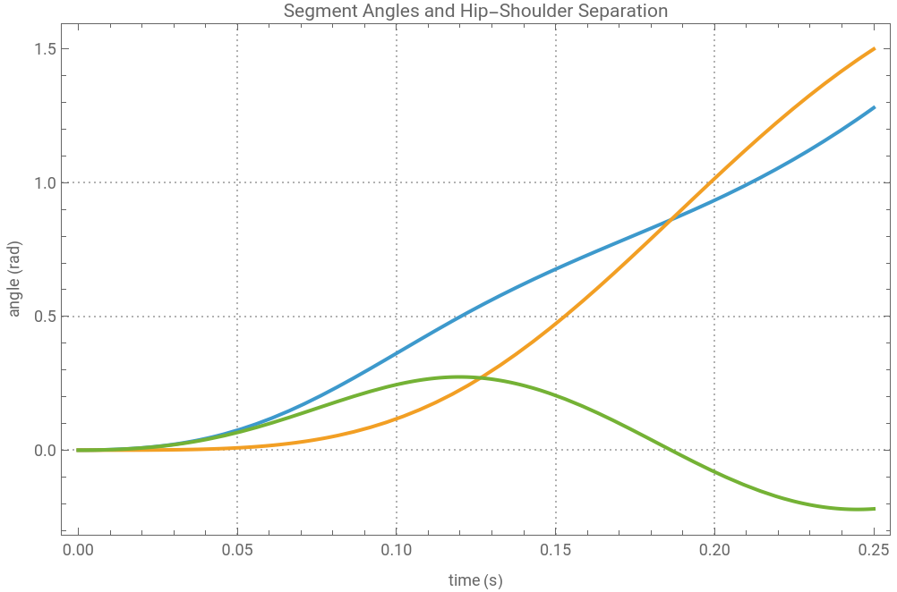
Tracking how far the pelvis and shoulders have each rotated over the course of the punch, along with the separation angle between them.
In[]:=
anglePlot=Plot[Evaluate[{thetaPsol[t],thetaSsol[t],phiSol[t]}],{t,0,tEnd},PlotLegends{"Pelvis angle θp","Shoulders angle θs","Hip-shoulder separation ϕ"},FrameLabel{"time (s)","angle (rad)"},PlotLabel"Segment Angles and Hip-Shoulder Separation",Evaluate[opts]];
Here we plot how fast each segment is rotating at every instant, for both the pelvis and the shoulders. This reveals the sequencing of the kinetic chain: the pelvis should peak in speed first, and the shoulders should peak later and faster, which is the signature of momentum being handed off from the lower body toward the fist.
In[]:=
velocityPlot=Plot[Evaluate[{omegaP[t],omegaS[t]}],{t,0,tEnd},PlotLegends{"Pelvis angular velocity ωp","Shoulders angular velocity ωs"},FrameLabel{"time (s)","angular velocity (rad/s)"},PlotLabel"Angular Velocities",Evaluate[opts]];
Next, we display the four rotational forces acting in the system over time, and this shows when and how strongly each contributor pushes the system, and how the core joint mediates between the lower and upper body.
In[]:=
torquePlot=Plot[Evaluate[{tauLegs[t],tauJointSol[t],tauActiveSol[t],tauArms[t]}],{t,0,tEnd},PlotLegends{"Legs/GRF torque","Core joint torque","Active core torque","Arms torque"},AxesTrue,FrameLabel{"time (s)","torque (N m)"},PlotLabel"Torques",Evaluate[opts]];
After that, we show the rate at which energy is transferred through the core joint at each moment.
In[]:=
powerPlot=Plot[Evaluate[corePower[t]],{t,0,tEnd},PlotLegends{"Core power"},AxesTrue,FrameLabel{"time (s)","power (W)"},PlotLabel"Power Flow Through Core Joint",Evaluate[opts]];
The first figure shows how far each segment has rotated as the punch unfolds. The pelvis angle θ_p and the shoulder angle θ_s both climb from zero, but the pelvis leads and the shoulders follow. The gap between the two curves is the hip-shoulder separation φ, plotted as the third line φ rises to a peak early in the motion, as the pelvis pulls ahead, and then falls back toward zero as the shoulders catch up and overtake. That rise-and-collapse of the separation curve explains the winding and unwinding of the coupling that stores and then releases energy into the shoulders.
In[]:=
anglePlot
Out[]=


Plotting the rotational speed of each segment at every instant.
Showing how the four rotational influences acting in the system over time, such that the timing of the drive can be read directly. The legs/ground-reaction torque (τ_legs) is the large, early pulse that initiates everything. The arms torque (τ_arms) is the smaller, later pulse that adds to shoulder rotation near the end of the motion. The active core torque (τ_active) is the muscular contribution generated by the Hill-type coupling, and the total core joint torque (τ_joint) is what actually passes between pelvis and shoulders.
Plotting the mechanical power crossing the core joint at each moment, which is the rate at which energy is being transferred between the two segments. When this curve is positive, energy is flowing from the pelvis into the shoulders; the area under that positive region is the total energy handed up the chain.
Numerical Outputs
Numerical Outputs
Here we find the largest hip–shoulder separation reached during the punch, and the moment it occurs.
Below we compute the fastest the shoulders rotate at any point in the punch, along with its timing . Since the shoulders sit closest to the fist in this two - segment model, this value is the best single indicator of how much rotational speed the chain delivers toward the strike .
We find the peak rotational speed of the pelvis and when it happens.
Next we determine the maximum rate of energy transfer through the core joint and the moment it occurs.
Finally, we collect the four peak results into a single labelled association, pairing each quantity with its value and timing so the key outcomes of the simulation can be read at a glance .
Visualisation
Visualisation
Now we can create an interactive 3D visualisation tool of the simulation.
Firstly, we need to create a helix spring between two 3D points.
Setting up the helper functions.
Next, we define an arc in a horizontal plane from angle a1 to a2, radius r, height z. It will be drawn to mark the angular gap between the pelvis and the shoulders:
z-landmarks of the two blocks, with 40 as the rest length. This will set the fixed vertical positions of the shoulder and pelvis segments along the body and the spring’s natural resting length:
As the time slider is dragged, the pelvis and shoulders should rotate about the body’s central axis as the simulation predicts, and every other element should respond in step. Next, two coloured blocks are implemented, which represent the two rigid segments of the model, the orange pelvis below and the blue shoulders above. An opaque stack of blocks between them will represent the trunk, twisting gradually from one to the other and making the hip–shoulder separation visible as a physical wind-up. The springs running between the segments change colour as they stretch when the trunk coupling is under the most strain, and a purple arc traces the separation angle at each instant. Velocity arrows grow and shrink with the rotational speed of each segment, giving a sense of which part of the body is moving fastest and when the shoulders overtake the pelvis. Finally, a simple jointed arm swings out from the shoulders to a red fist to produce a strike. The panel of sliders and checkboxes lets the reader change the body’s proportions, adjust the arm’s posture, and switch each feature on or off, so they can isolate whichever aspect of the mechanism they want to understand.
Video Experiment
Video Experiment
Experimental Design
Experimental Design
Aim
Aim
For my project, I conducted a video experiment to help me conduct the kinematic and kinetic analysis of the boxing cross. The aim was to obtain time-resolved kinematic data (position, and hence velocity and acceleration, of tracked body-segment markers) and kinetic data (impact force on a struck target of known mass) during a boxing cross, and to use these data to test the proposed model of force generation in the punch.
Subjects
Subjects
Apparatus
Apparatus
◼
One high-frame-rate (60fps) camera capable of slow - motion capture (primary camera)
◼
A plain, uniform-colour background wall
◼
Rigid target/pad of known mass to be struck (2 boxing pads + tape; measured mass 0.72 kg)
◼
Brightly-coloured circular markers (trackers) for placement on body segments and target
Experimental Setup
Experimental Setup
The camera is mounted with its image plane parallel to the background wall and directed squarely at it. The subject is positioned centrally in the camera’s field of view (i.e. in the middle of the frame). Frame boundaries define the usable capture region; the subject and the full extent of the punch trajectory must remain within these boundaries throughout the motion.
The subject stands in a standard boxing stance with the weak (leading) hand held forward as the jab hand, so that the rear crossing hand is the hand nearest the camera. The cross therefore travels approximately within (parallel to) the camera’s image plane, which minimises out-of-plane (depth) motion of the tracked markers.
Figure 1.
Top-down view (camera image plane parallel to the wall; subject 1 (Warren) centred
Top-down view (camera image plane parallel to the wall; subject 1 (Warren) centred
Video Processing
Video Processing
Setup
Setup
Importing an internal package that defines algebraic data types and structural schemas :
Importing videos for each subject:
Video Information
Video Information
Extracting useful information from the videos:
Processing Videos
Processing Videos
Setting up an Association to store parameters for each subject. The coordinates stored for each subject represent a boxed region that is used later for tracking the movement of the shoulders and hips during the punching motion.
Next, we should set up a function that takes a filmed punch and pulls out the movement of the puncher’s hips and shoulders throughout the strike. It produces two visual outputs, a still frame with the tracked paths of the hips and shoulders drawn over it, and a slider to control the frame, in order to track the motion of the pelvis and shoulders.
Calling the function for subject 1.
Experimental Validation
Experimental Validation
First, let us work out how many frames per second a video was filmed at, which is what allows frame numbers to be converted into real time in seconds
Creating a helper function to query the video’s frame-rate metadata, and if that is unavailable, falls back to dividing the total frame count by the video’s duration in seconds.
Next, we need to gather everything needed to analyse one filmed subject into a single tidy package: the frames, the tracked positions of the hips and shoulders, which frames were tracked cleanly, and the frame rate.
For each validly tracked frame we need to take the vector from the hip centroid to the shoulder centroid. We need to use ArcTan to recover that vector’s angle, and pairs those angles with a time axis.
Next, we need to measure the time delay between the hips reaching peak speed and the shoulders reaching peak speed. A positive lag means the pelvis leads and the shoulders follow, which is the very proximal-to-distal sequencing the model is built to capture.
Overlaying the separation angle measured from one real punch directly on top of the model’s simulated separation curve. Both curves are normalised so that the comparison is about the shape and timing of the motion rather than absolute magnitudes.
Rescaling one subject’s separation curve so that every punch runs from 0 to 1 in time, letting punches of different lengths and speeds be compared on equal footing.
Applying the normalisation above to every filmed subject at once, producing a common set of separation curves ready to be compared side by side.
Mapping subjectData and then normalisedSeparation over the four tracked subjects.
Plotting the normalised separation curves of all four boxers together.
Each curve represents the hip-shoulder separation over the duration of the punch. From the output obtained above, they all follow a similar three-part structure. In the first stage, separation stays close to zero, as all subjects are in a boxing stance, with roughly no movement of the hips and shoulders (relative to each other). In the second stage, the pelvis rotates ahead of the shoulder, resulting in a sharp increase of angular separation. Then there is a sharp reversal near the end as the trunk unwinds and the shoulders catch and overtake the pelvis. This structure accurately represents the initial proposed model, where the separation opens as the proximal segment leads, stores rotational energy in the trunk coupling, and then collapses as that energy is handed distally toward the fist.
Analysis of the Dynamic System
Analysis of the Dynamic System
Euler-Lagrange Derivation Proof
Euler-Lagrange Derivation Proof
The equations of motion from my mathematical model were derived from Newton’s second law for rotation. It can be proven that those same equations follow from Lagrangian mechanics. Therefore, let us re-derive the equations of motion from a completely different starting point.
The same equations can be rebuilt from energy instead, using Lagrangian mechanics, which makes use of the system’s kinetic energy and the conservative spring potential. For two bodies rotating about a shared vertical axis, the kinetic energy and the conservative spring potential are:
The same equations can be rebuilt from energy instead, using Lagrangian mechanics, which makes use of the system’s kinetic energy and the conservative spring potential. For two bodies rotating about a shared vertical axis, the kinetic energy and the conservative spring potential are:
The spring is conservative. This means that the effects of damping, muscle active muscle torque, and the leg pulses are ignored. if the two approaches genuinely describe the same physics, that must mean they must yield identical equations. Applying the Euler-Lagrange equation
should reproduce my Newtonian equations exactly.
Let us begin by setting up the energy description of the system, which is the kinetic energy of the two rotating segments minus the elastic potential energy stored in the trunk coupling. We then apply the Euler-Lagrange operation to each segment to obtain the left-hand side of its equation of motion, purely from energy considerations.
Clearing the relevant symbols, defining Lag as ½Ip θp′² + ½Is θs′² − ½k(θs − θp)², and computing ELp and ELs by taking, for each coordinate, the time derivative of ∂L/∂θ′ minus ∂L/∂θ.
Defining the non-conservative joint torque tauJointNC. Forming the generalised forces Qp and Qs for the pelvis and shoulders, and using Simplify to subtract the earlier Newtonian right-hand sides from ELp − Qp and ELs − Qs.
Conclusion
Conclusion
In this research project, we explained the boxing cross as the outcome of a proximal-to-distal kinetic chain and placed hip–shoulder separation at the centre of that explanation, not solely the arm. By reducing the trunk to two rigid segments coupled by a single torque-producing joint, the model captured the essential mechanism: the legs drive the pelvis, the pelvis rotates ahead of the shoulders, and the elastic winding of the coupling stores energy that is later released to accelerate the upper body toward the fist. Despite its deliberate simplicity, this reduced-order representation reproduced the behaviour that defines an effective punch.
The simulation confirmed the sequencing that a kinetic chain predicts. The pelvis peaked in angular velocity first, followed by a later and faster peak in the shoulders. Subsequently, this demonstrated that momentum is handed from the lower body to the upper body rather than generated locally at the arm. The separation angle behaved as a genuine mechanical intermediary. It rose as the pelvis led, then collapsed as the coupling discharged its stored energy into shoulder rotation. Tracking the mechanical power through the core joint made this energy transfer explicit, which showed precisely when and how strongly the chain delivers rotational speed toward the strike.
The video experiment provided time-resolved kinematic data from marker tracking and a measured impact force on a target of known mass. Consequently, it allowed the simulated dynamics to be tested against a real punch rather than assumed. This validation step is what separates a plausible model from a supported one, and it grounded the abstraction in observable, measurable movement. The final Euler–Lagrange derivation offered a second, independent confirmation. This was achieved by recovering the equations of motion (first obtained from Newton’s second law for rotation) from Lagrangian mechanics. Taken together, these results support the central claim that hip–shoulder separation is the mechanism carrying momentum through the chain. It also supports the idea that the same multibody-dynamics abstraction used to describe humanoid robots can be used to meaningfully describe a human punch. The strength of the cross lies not in the arm alone but in the coordinated, correctly timed sequencing of the whole body, a principle that is as relevant to controlling a machine’s joints as it is to throwing a punch.
Future Directions
Future Directions
The model’s strength is also its main limitation. Reducing the trunk to two rigid segments rotating about a single shared axis discards much of the body’s real complexity. The legs and arms were represented as prescribed Gaussian torque pulses rather than modelled explicitly. Other issues being the fact that out-of-plane motion was neglected, and the coupling parameters were drawn from general anthropometric data rather than measured from the individual being filmed. Each of these is a deliberate simplification that trades fidelity for insight.
Future work could relax these assumptions in stages. Adding further segments such as a full lower-limb and arm chain, or a multi-joint spine, would let the ground-reaction and arm torques emerge from the dynamics instead of being imposed. Extending the motion into three dimensions would capture the flexion and lateral components that a transverse-plane model cannot. Most valuably, fitting the stiffness, damping and inertia parameters directly to each subject’s tracked video data would turn the model from a general description into a personalised one.
That last step is where the project’s scope becomes most compelling. A model that can be tuned to an individual from non-invasive video alone is a tool for understanding how a specific body generates and transmits force. The same framework that sequences a punch describes any explosive rotational movement, and the underlying principle which encompasses the idea that coupled segments storing and releasing elastic energy in a timed chain, extends naturally to rehabilitation, injury prevention, and the design of assistive or prosthetic devices that must reproduce coordinated human motion.
Ultimately, the value of this approach lies in bridging measurable human movement and predictive mechanical modelling. Refining that bridge, so that a simulation can be built and validated from ordinary footage of a real person, is the direction most worth pursuing.
References
References
◼
Thomas, S. J., Zeni, J. A., & Winter, D. A. (2023). Winter’s biomechanics and motor control of Human Movement. John Wiley & Sons, Inc.
◼
Sha L, Chiu WH. Wearable Sensor-Based Analysis of Punch Acceleration and Plantar Pressure Distribution in Boxing. Sensors. 2026; 26(9):2707. https://doi.org/10.3390/s26092707
◼
10.7 Newton’s Second Law for rotation - university physics volume 1 | openstax. (n.d.). https://openstax.org/books/university-physics-volume-1/pages/10-7-newtons-second-law-for-rotation
◼
Kacprzak, J., Mosler, D., Tsos, A., & Wąsik, J. (2025). Biomechanics of Punching—The Impact of Effective Mass and Force Transfer on Strike Performance. Applied Sciences, 15(7), 4008. https://doi.org/10.3390/app15074008
◼
Han, K. H., Como, C., Kim, J., Hung, C. J., Hasan, M., & Kwon, Y. H. (2019). Effects of pelvis-shoulders torsional separation style on kinematic sequence in golf driving. Sports biomechanics, 18(6), 663–685. https://doi.org/10.1080/14763141.2019.1629617
Acknowledgements
Acknowledgements
I’d like to thank Anton Antonov, my mentor, for his tremendous support and incredible guidance, for helping me throughout the entirety of my project. His expertise in karate and understanding of the human kinetic chain was what made this project possible. I’d also like to express my gratitude to Stephen Wolfram and the directors for organising the research program. A big thank you to Lucas Squillante for spending his time helping me record the punches, and I’d also like to thank Eric Archerman, Anton Antonov, Eileen Lee, and Warren Chen for being such great models for the punching motion videos. Finally, thank you to my TA group, my TA Bryan, and my mentor group for making these two weeks so memorable.
CITE THIS NOTEBOOK
CITE THIS NOTEBOOK
Analysing the rotational kinetic chain of a cross punch
by Nicholas Zhan
Wolfram Community, STAFF PICKS, July 9, 2026
https://community.wolfram.com/groups/-/m/t/3753019
by Nicholas Zhan
Wolfram Community, STAFF PICKS, July 9, 2026
https://community.wolfram.com/groups/-/m/t/3753019