In this short computational essay, I explore the Grover’s algorithm and its implementation in the Wolfram Quantum Framework. I showed different way of implementing the Grover oracle (e.g., the Boolean oracle or phase shift oracle) and also explored how the probability of success for this algorithm varies depending on different circuit construction and the initial state of ancillary qubits (being used for the oracle space), if any.
Paclet installation
Paclet installation
PacletInstall[CloudObject["https://wolfr.am/DevWQCF"], ForceVersionInstall -> True]<< Wolfram`QuantumFramework`
Out[]=
PacletObject

Boolean oracle operator/circuit
Boolean oracle operator/circuit
The action of a Boolean oracle is defined by this transformation: with the index register state of n-qubits, and the state of an ancillary qubit carrying the result of Boolean function ; meaning if then it will be if x is a solution of f(x), and no change if not.
|x〉|q〉->|x〉|q⊕f(x)〉
|x〉
|q〉
f(x)
|q〉=|0〉
|1〉
Define a Boolean function of 3-SAT with 5 clauses:
In[]:=
f=And[!v1||!v2||!v3,v1||!v2||v3,v1||v2||!v3,v1||!v2||!v3,!v1||v2||v3];
Truth table of above Boolean function:
ResourceFunction["TruthTable"][f,{v1,v2,v3}]
Out[]=
v1 | v2 | v3 | (!v1||!v2||!v3)&&(v1||!v2||v3)&&(v1||v2||!v3)&&(v1||!v2||!v3)&&(!v1||v2||v3) |
True | True | True | False |
True | True | False | True |
True | False | True | True |
True | False | False | False |
False | True | True | False |
False | True | False | False |
False | False | True | False |
False | False | False | True |
Corresponding oracle’s quantum circuit:
In[]:=
oracle=QuantumCircuitOperator[{"BooleanOracle",f}];
The diagram of oracle:
oracle["Diagram"]
Out[]=
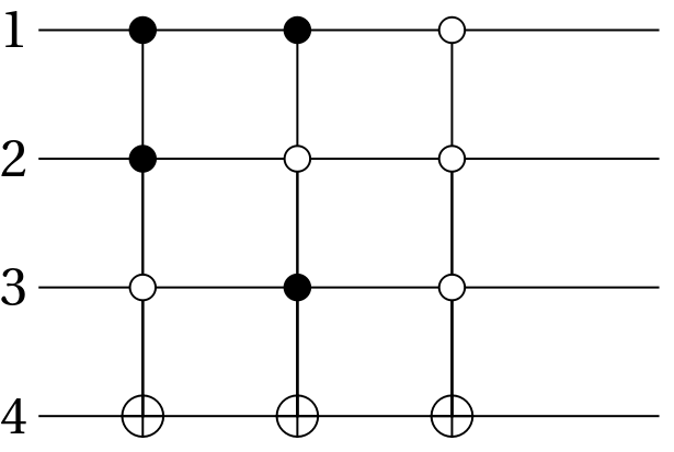
We shall prepare the 4-qubit in above circuit (ie the ancillary qubit) is 0 state, and then other qubits (1-3) in the index register states. To compare with above truth table, we will create the index register states |x> in the order down to |0>
|-1>
n
2
In[]:=
states=QuantumTensorProduct[#,QuantumState["0"]]&/@Table[QuantumState[{"Register",3,i}],{i,2^3-1,0,-1}];
Create a list with elements {|x>,|q⊕f(x)}:
TableForm[Transpose[{Table[QuantumState[{"Register",3,i}]["Formula"],{i,2^3-1,0,-1}],QuantumPartialTrace[oracle[#],{1,2,3}]["Formula"]&/@states}],TableHeadings{None,{"|x>","|q⊕f(x)>"}}]
Out[]//TableForm=
|x> | |q⊕f(x)> |
|111〉 | |0〉 |
|110〉 | |1〉 |
|101〉 | |1〉 |
|100〉 | |0〉 |
|011〉 | |0〉 |
|010〉 | |0〉 |
|001〉 | |0〉 |
|000〉 | |1〉 |
As one can see, the oracle circuit reproduce the same result as the classical ones.
If the initial state of the ancillary qubit is |->, the overall effect of the oracle will be adding - sign in front of |x> with x the solution of Boolean function
In[]:=
states=QuantumTensorProduct[#,QuantumState["Minus"]]&/@Table[QuantumState[{"Register",3,i}],{i,2^3-1,0,-1}];
Create a list with elements as {|x,->, oracle|x,->}:
In[]:=
results=Transpose[{states,oracle/@states}];
Test {|x>, oracle|x>} are physically the same:
Equal@@@results
Out[]=
{True,True,True,True,True,True,True,True}
Given |x> as an index register state of 3-qubits, create a list with elements {|x>,<-|oracle|x,->}:
TableForm[Transpose[{Table[QuantumState[{"Register",3,i}]["Formula"],{i,2^3-1,0,-1}],QuantumOperator[QuantumState["Minus"]["Dagger"],{4}][#]["Formula"]&/@oracle/@states}],TableHeadings{None,{"|x>","oracle|x>"}}]
Out[]//TableForm=
|x> | oracle|x> |
|111〉 | |111〉 |
|110〉 | -|110〉 |
|101〉 | -|101〉 |
|100〉 | |100〉 |
|011〉 | |011〉 |
|010〉 | |010〉 |
|001〉 | |001〉 |
|000〉 | -|000〉 |
As expected, only the solutions get a phase shit -1. Note we have calculated that shift quantum mechanically.
Phase oracle operator/circuit
Phase oracle operator/circuit
The action of a phase oracle can be defined as the following transformation: with the index register state of n-qubits,
xx
f(x)
(-1)
|x〉
Define a Boolean function of 3-SAT with 4 clauses:
In[]:=
f=And[!v1||!v2||!v3,v1||!v2||v3,v1||v2||!v3,v1||!v2||!v3];
Truth table of above Boolean function:
ResourceFunction["TruthTable"][f,{v1,v2,v3}]
Out[]=
v1 | v2 | v3 | (!v1||!v2||!v3)&&(v1||!v2||v3)&&(v1||v2||!v3)&&(v1||!v2||!v3) |
True | True | True | False |
True | True | False | True |
True | False | True | True |
True | False | False | True |
False | True | True | False |
False | True | False | False |
False | False | True | False |
False | False | False | True |
Corresponding oracle’s quantum circuit:
In[]:=
phaseOracle=QuantumCircuitOperator[{"PhaseOracle",f}];
The diagram of oracle:
phaseOracle["Diagram"]
Out[]=
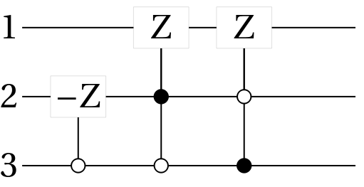
We shall prepare the 3-qubit in the index register states. To compare with above truth table, we will create the index register states |x> in the order down to |0>
|-1>
n
2
In[]:=
states=Table[QuantumState[{"Register",3,i}],{i,2^3-1,0,-1}];
Create a list with elements |x>}:
x>,
f(x)
(-1)
TableForm[Transpose[{Table[QuantumState[{"Register",3,i}]["Formula"],{i,2^3-1,0,-1}],phaseOracle[#]["Formula"]&/@states}],TableHeadingsNone,"|x>","-1|x>"]
f(x)
)
Out[]//TableForm=
|x> | -1 f(x) ) |
|111〉 | |111〉 |
|110〉 | -|110〉 |
|101〉 | -|101〉 |
|100〉 | -|100〉 |
|011〉 | |011〉 |
|010〉 | |010〉 |
|001〉 | |001〉 |
|000〉 | -|000〉 |
As one can see, the oracle circuit reproduce the same result as the classical ones.
Grover circuit with phase or Boolean oracles
Grover circuit with phase or Boolean oracles
Let’s define a Boolean function with only one solution (note in our framework, it does not matter if one or more solutions)
Generate the corresponding Grover circuit using a phase oracle:
Generate the corresponding Grover circuit using a phase oracle, this time with controlled-0 conditional gates:
Generate the corresponding Grover circuit using a Boolean oracle:
Generate the corresponding Grover circuit using a Boolean oracle, this time with controlled-0 conditional gates:
The probability of success for the Grover algorithm
The probability of success for the Grover algorithm
We shall consider the following Boolean function and will explore different cases and how the probability of success of the algorithm depends on circuit design or the initial state of ancillary qubit.
Grover circuit with the Boolean oracle
Grover circuit with the Boolean oracle
Ancillary in |x->
Ancillary in |x->
the oracle above has the state |111111> as the solution (which is |x=2^6-1>)
Initial state for the circuit (qubit 1-6, each one in |x+>, and the ancillary qubit in |x->)
applying Grover iteration 20 times
Define a function returning Grover probability of success:
Calculate the probability of success for above circuit
Compare the difference percentage of in the probability of success we get from above formula with the one from the circuit above:
Ancillary in |0>
Ancillary in |0>
Initial state for the circuit (qubit 1-6, each one in |x+>, and the ancillary qubit in |0>)
applying Grover iteration 20 times
Grover with phase shift circuit (no ancillary qubit)
Grover with phase shift circuit (no ancillary qubit)
the oracle above has the state |111111> as the solution (which is |x=2^6-1>)
Initial state for the circuit (qubit 1-6, each one in |x+>)
applying Grover iteration 20 times
Calculate the success probability after each iteration:
Plot the success probability:
Contact
Contact
Please explore the Wolfram Quantum Framework and share with feedback or suggestion: quantum AT wolfram.com