Introduction
Introduction
New version of System Modeler, new version of the Aircraft Library!
◼
Wolfram System Modeler 14.0: A drag-and-drop modeling and simulation environment for cyber-physical systems based on the Modelica language.
◼
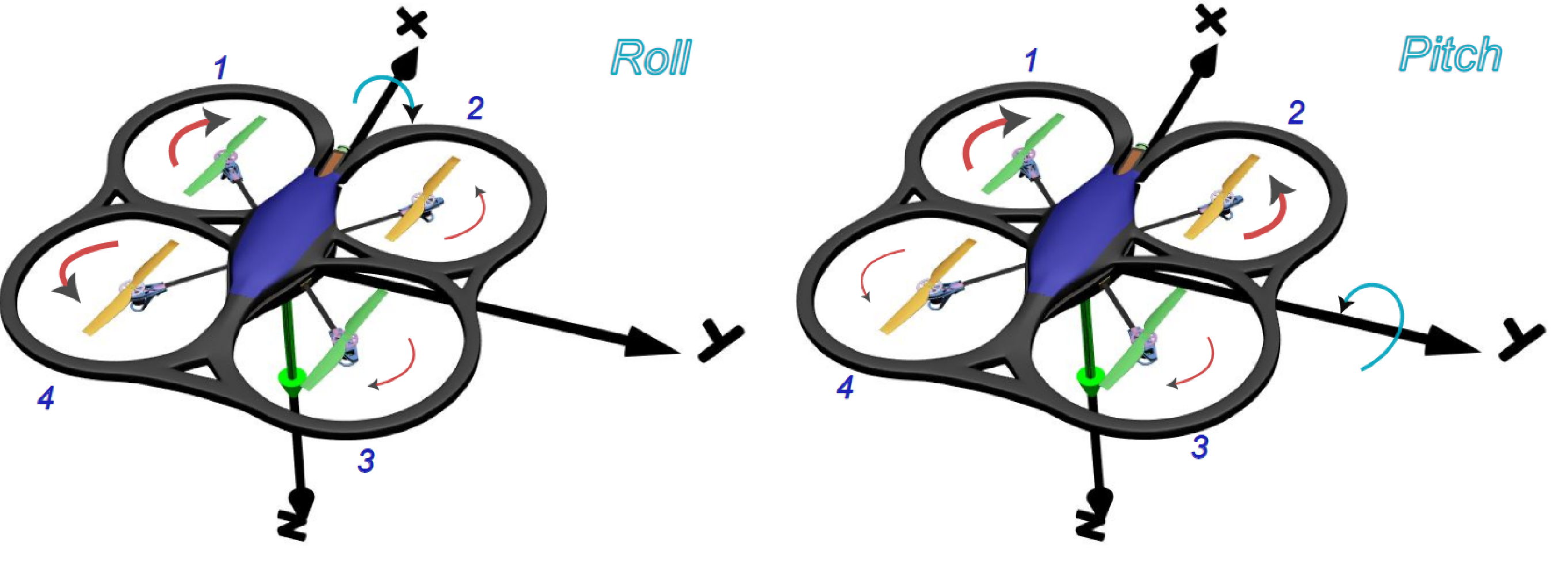
New in the Aircraft Library 2.0: RotaryWing (drones) and redefined structure for fixed-wing airplanes.

RotaryWing Package
RotaryWing Package
◼
Model an existing quadrotor, your own design or tune an autopilot.
◼
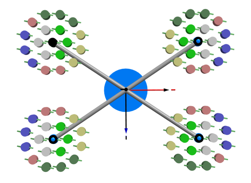
Possibilities: Model a 76-rotor drone.
Physical Fixed-Wing Package
Physical Fixed-Wing Package
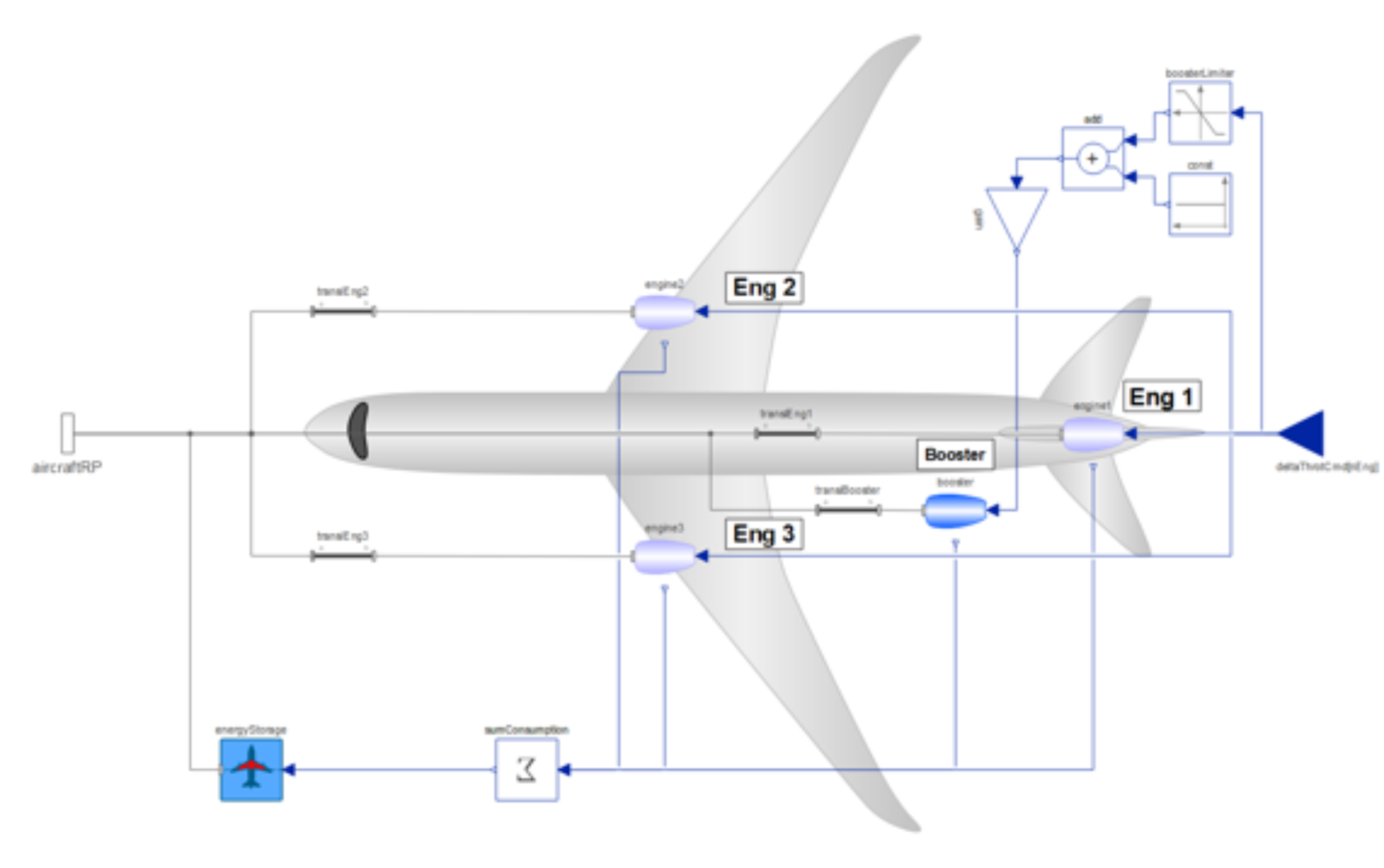
Contrary to the conventional state-space linearized model, airplanes in the Aircraft Library 2.0 use the Modelica MultiBody elements.
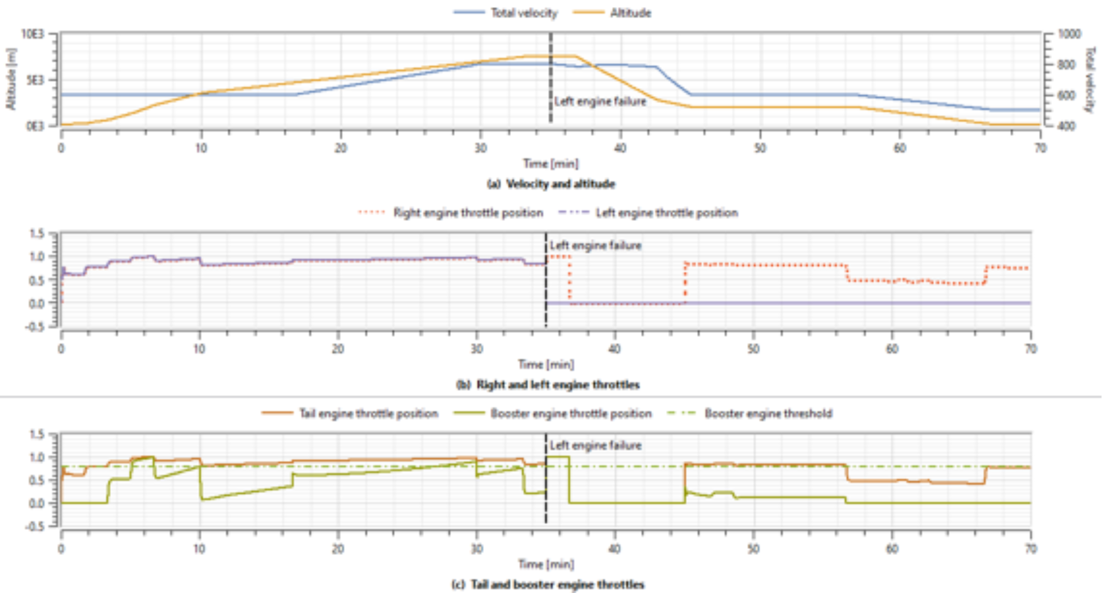
Aircraft Library 2.0 allows:
◼
Complex task done in a simple way.
◼
Get insights into your airplane from the very beginning!
Modeling of Today: The Italian Frecce Tricolori
Modeling of Today: The Italian Frecce Tricolori
The aerobatic demonstration team of the Italian Air Force.
◼
Today’s model: Aermacchi MB339.
◼
The aircraft is a two-seat advanced trainer military jet aircraft.
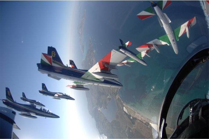
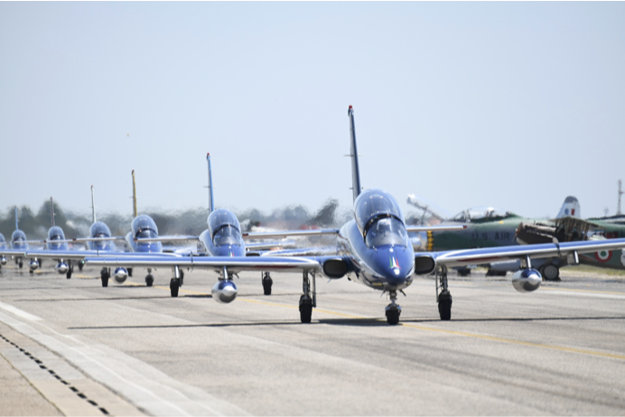
Image credits: Aeronautica Militare. Retrieved from: https://www.aeronautica.difesa.it/home/noi-siamo-l-am/personale-e-mezzi/pattuglia-acrobatica-nazionale
Modeling Aerobatics
Modeling Aerobatics
Aerobatics is the practice of flying maneuvers involving aircraft attitudes that are not used in conventional flights.
Video credits: Aeronautica Militare - Il volo folle del solista delle Frecce Tricolori. Publicly available at: https://www.youtube.com/watch?v=DUkbDvWcfwI
Forces in an Airplane in Equilibrium
Forces in an Airplane in Equilibrium
On straight and level unaccelerated flight, forces are in equilibrium.
◼
Lift equals weight, and thrust equals drag.
G-Forces
G-Forces
Because of the interplay among lift, weight and centrifugal forces during maneuvers, the pilot and the airframe are subjected to acceleration changes.
This is measured in g’s, where at 1 g the airplane and pilot “weigh” the same as static, at 2 g they weigh double, etc.
◼
Pilots in a high-G maneuver feel as if “an elephant is sitting on top of them.”
◼
Pilots in zero G experience the same as astronauts.
◼
Pilots in negative G feel they are being pulled down (my personal favorite), similar to a rollercoaster drop.
The load factor measures the relationship between lift (changing dependant on maneuver) over weight (always constant, pointing to the ground).
Doing some algebra, load factor becomes only a function of the bank angle.
But why does this happen?
Forces during a Turn
Forces during a Turn
Turning is done when banking: rolling the airplane around the axis that runs from nose to tail using ailerons.
◼
When banking, the lift force (always perpendicular to the wings) decomposes into a vertical and a horizontal.
◼
By Newton’s third law, the force that opposes the horizontal component of lift is the centrifugal force.
◼
While weight remains the same, turning the aircraft effectively increases the load applied to it.
◼
The higher the bank, the higher the load!
◼
Valid for equilibrium, at constant velocity and neglecting control surface coupling interactions.
Pilot’s Point of View during a Turn
Pilot’s Point of View during a Turn
Linköping SAAB’s JAS-39 Gripen performing tight turns. The G-meter shows the acceleration the pilot and airplane are subjected to.
Video credits: Gripen and the G Force. SAAB. Publicly available at: https://www.youtube.com/watch?v=eXaPfUs6sQw
Forces during a Pull-Up: Positive G
Forces during a Pull-Up: Positive G
A sudden increase in lift will make the airplane go upward.
◼
The tighter the turn radius, the higher the positive loads.
Forces during an English Blunt: Negative G
Forces during an English Blunt: Negative G
A sudden pull-down will increase lift in the weight direction.
◼
The tighter the turn radius, the higher the negative load.
Pilot’s Point of View during Pull-Up and Pull-Down
Pilot’s Point of View during Pull-Up and Pull-Down
SAAB’s JAS-39 Gripen performing loops.
Video credits: Gripen and the G Force. SAAB. Publicly available at: https://www.youtube.com/watch?v=eXaPfUs6sQw
The V-n Diagram
The V-n Diagram
A velocity vs. load factor diagram allows pilots to know where it is structurally safe to fly.
◼
The curved lines show aerodynamic limitations, while the straight lines show structural limitations.
◼
It is not symmetric: both the pilot and the airplane withstand positive loads better.
Conclusions
Conclusions
◼
The new capabilities of the Aircraft Library 2.0 were presented.
◼
These include the RotaryWing (drone) package and the redesigned structure of the library.
◼
The 6 degrees of freedom rigid body modeling allows testing for structural limit integrity when performing maneuvers.
◼
This can be coupled with all the resources from Wolfram System Modeler’s existing libraries!
References
References
◼
Anderson, J. D. (2012). Introduction to Flight (7th ed.). McGraw-Hill Education.
◼
Nelson, R. C. (1998). Flight Stability and Automatic Control. 2nd ed. McGraw-Hill.
◼
Cook, M. A. (2012). Flight Dynamics Principles. (3rd ed.) Butterworth Heinemann.
◼
Erä-Esko, N. (2022). Development and Use of System Modeler 6DOF Flight Mechanics Model in Aircraft Conceptual Design, master’s thesis.
◼
CITE THIS NOTEBOOK
CITE THIS NOTEBOOK
Simulating high-G jet aerobatics with Wolfram System Modeler's Aircraft Library 2.0
by Erick Espinosa-Juárez and Vedat Şenol
Wolfram Community, STAFF PICKS, June 24, 2024
https://community.wolfram.com/groups/-/m/t/3198862
by Erick Espinosa-Juárez and Vedat Şenol
Wolfram Community, STAFF PICKS, June 24, 2024
https://community.wolfram.com/groups/-/m/t/3198862