The Graham Clock Escapement
The Graham Clock Escapement


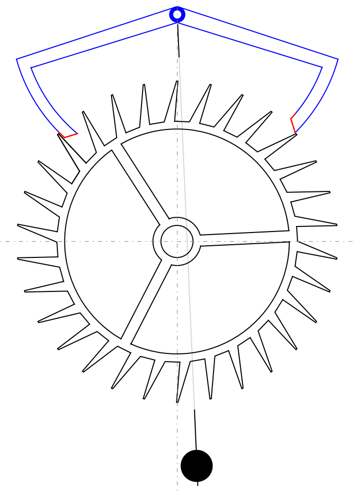
A clock escapement regulates the progress of the gear train that eventually moves the clock hands. The escapement effectively counts the number of swings made by the pendulum.
The escapement in this Demonstration is the Graham dead-beat escapement. The wheel is stopped by the anchor's pallets (lock phase) and remains stationary up to the instant of its unlocking (impulse phase).
Details
Details
A basic clock escapement consists of an anchor and an escape wheel. The pallets at the end of the anchor's arms (in red in this Demonstration) are the essential parts of an escapement. Their shape and position greatly determine its effectiveness. Two angles, measured as drawn from the axis of the anchor, are important: the impulse angle determines the time the escape wheel is moving, and the lock angle sets the time the wheel is stopped. To allow for geometrical conflicts or mechanical inaccuracies, a "drop angle" can be added to the anchor's movement.
For a complete treatise on clock escapements, see[1].
References
References
[1] M. V. Headrick. "Clock and Watch Escapement Mechanics." (1997) www.abbeyclock.com/EscMechanics.pdf.
Permanent Citation
Permanent Citation
Erik Mahieu
"The Graham Clock Escapement"
http://demonstrations.wolfram.com/TheGrahamClockEscapement/
Wolfram Demonstrations Project
Published: January 16, 2013