Theoretical approaches to representing discrete operators as linear state space transformations, a proof of classical universality, and a proposed smallest 22 universal quantum gate set. This computational essay explores universal classical and quantum gates. It formulates classical operations in terms of linear algebra, which allows it to also be applied to quantum gates, and implements a quantum computing simulator which can run both classical and quantum circuits. Using this formulation of universality, a proof of the 22 case is set out which shows that NAND and NOR are the only possible individually universal classical gates. Finally, this paper sets out a novel minimal set of 22 quantum gates which may be the smallest such set ever found, and proves that set’s universality under an input initialized based on the classical construction of the universality problem.
Introduction
Introduction
Universal Classical Gates
Universal Classical Gates
Classical logic uses logical operators, called gates, that transform one or more boolean-valued inputs to one or more boolean-valued outputs. For example, the AND gate returns True only when both of it’s inputs are True. AND is of the form 21, because it takes in two inputs and returns a single output.
An operation of two boolean values can be represented by a truth table, with each axis representing each input.
An operation of two boolean values can be represented by a truth table, with each axis representing each input.
Truth Table Implementation
Truth Table Implementation
Example
Example
In[]:=
truthTable[And]
Out[]=
And | 0 | 1 |
0 | 0 | 0 |
1 | 0 | 1 |
Some gates are able to be composed with themselves to make any other possible gate. These gates are called universal gate.There are only two universal, classical, 21 gates, as will be proved later on: NAND (⊼) and NOR (⊽). For example, here is how the NAND gate can represent the XOR gate with a circuit diagram and code:
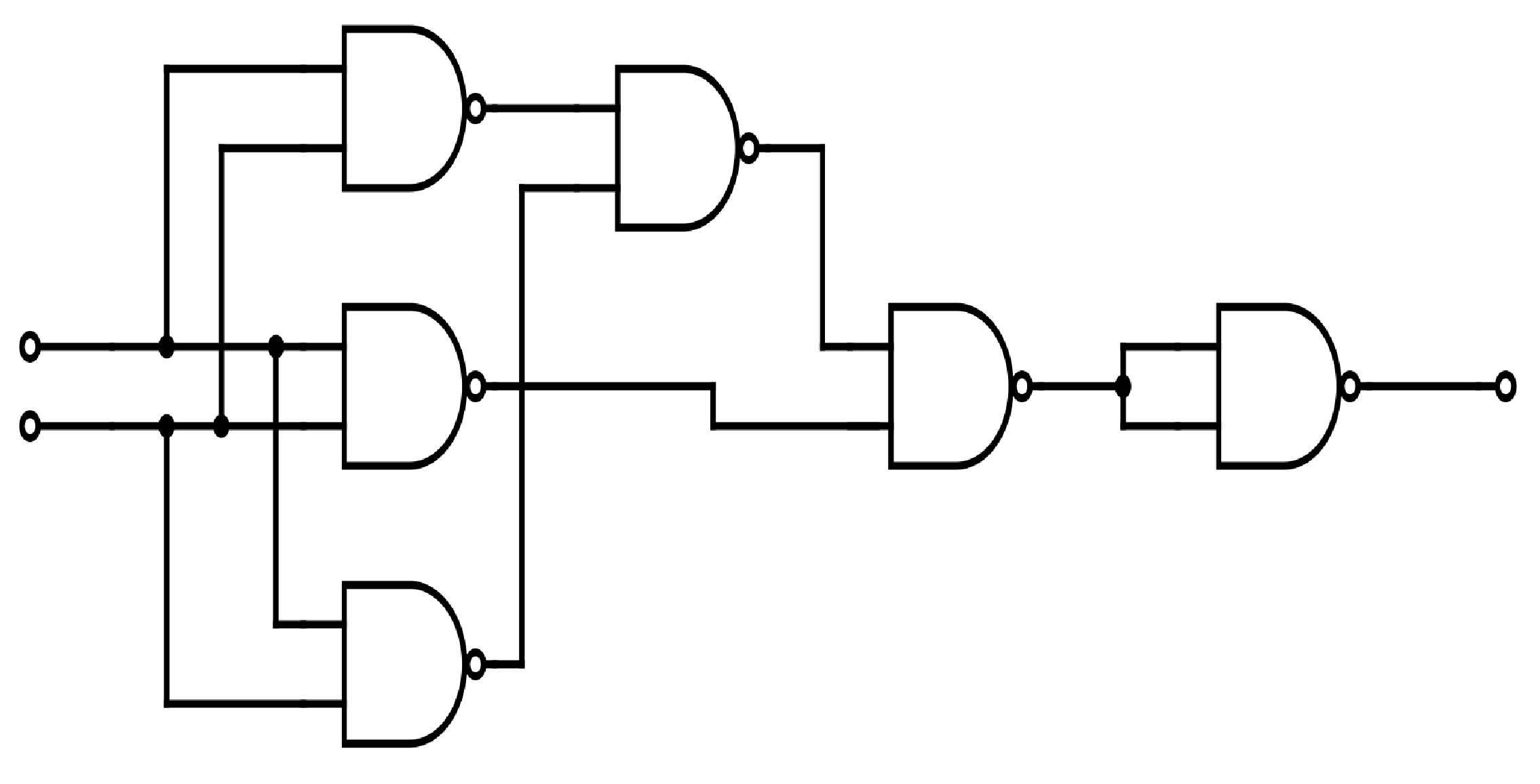
In[]:=
(*XORfromNANDgates*)xorFromNand[a_,b_]:=(((a⊼a)⊼(b⊼b))⊼(a⊼b))⊼(((a⊼a)⊼(b⊼b))⊼(a⊼b));(*DisplayTruthTables*)Row[{truthTable[Xor,"Xor Built-In"],Spacer[10],truthTable[xorFromNand,"Xor from Nand"]}]
Out[]=
Xor Built-In | 0 | 1 |
0 | 0 | 1 |
1 | 1 | 0 |

Xor from Nand | 0 | 1 |
0 | 0 | 1 |
1 | 1 | 0 |
Here is every symmetric logical gate implemented with the built-in function, with only NANDs, and with only NORs:
Out[]=
|
|
|
|
|
| ||||||||||||||||||||||||||||||||||||||||||||||||||||||
|
|
|
|
|
| ||||||||||||||||||||||||||||||||||||||||||||||||||||||
|
|
|
|
|
|
State Vector Representation of Operations
State Vector Representation of Operations
Classical 21 gates are usually considered to be a function with two inputs and one output. However, there is an alternative interpretation of gates as a linear operation on a unit basis vector representing the systems total state. This allows for all operations to be represented as matrix multiplications, and generalizes easily to quantum circuits.
State Vector
State Vector
◼
Let be the set of binary numbers {0, 1} .
An n-bit system can be represented with a vector in , such that each dimension of the vector corresponds to a bit in the state. A gate can be considered to be an association of each input state—of the total possible states—to a specific output state.A vector can be constructed in so that each dimension corresponds to a possible state. Thus, a unit basis vector of represents one singular state. A matrix transforms the ith basis vector to the ith column in the matrix .
n
n
2
n
2
n
2
e
i
V
i
For example, in the 4-bit binary system 1011, there are 16 possible states, so the 16-dimensional state vector representing this system is [
].
Note that the state vector of the binary number n (11 in this example) is the basis vector, assuming the vector is indexed from 0.
4
2
0 | 0 | 0 | 0 | 0 | 0 | 0 | 0 | 0 | 0 | 0 | 1 | 0 | 0 | 0 | 0 |
Note that the state vector of the binary number n (11 in this example) is the basis vector
e
n
Gate Application to a State Vector
Gate Application to a State Vector
A matrix M = [
], where ∈, takes the ith basis vector to (i.e., ).This means that M can associate each basis vector to a specific output vector , so, by our definition of a gate operation, this matrix can apply any arbitrary gate.
V 0 | V 1 | V 2 | V 3 | V 4 | V 5 | V 6 | V 7 | V 8 | V 9 | V 10 | V 11 | V 12 | V 13 | V 14 | V 15 |
V
i
n
2
V
i
M=
e
i
V
i
e
i
V
i
Motivation
Motivation
The reason for representing gates as matrix multiplication is two-fold:Firstly, in this representation, all gates are linear transformations, which can be easily composed and reasoned about. A whole circuit, made up of many gate operations, can be simplified to just a single matrix. Thus, the problem of determining whether a set of gates is universal is equivalent to the problem of whether every gate matrix can be decomposed into a product of elements in that set.Secondly, quantum systems exhibit phenomena such as superposition and entanglement, in which a quantum state may be in a linear combination of multiple states at the same time, and in which a full state can not be represented as the tensor product of individual qubit states, respectively. This means that an n-bit quantum state can be represented by a vector on the complex unit hypersphere of . The reason it must be on the unit hypersphere is because the magnitude of the vector must be equal to one, which is equivalent to the statement that the sum of the probabilities of the states of a random system is one.
n
2
Universal Quantum Gate Sets
Universal Quantum Gate Sets
Universal quantum gates should be able to recreate any possible other quantum gate. However, due to the fact that quantum state vectors are complex, there is a continuous space of possible gates, which cannot be described exactly by a finite universal set. For example, the arbitrary Z rotation gate (θ)=
is a valid quantum gate for any choice of θ.Instead, a universal quantum gate set is defined as one which can approximate any quantum gate to within some error factor ε. Formally, in order to represent a target gate T in terms of the finite gate set ,, for some appropriate matrix norm, such as the maximum L2 norm of the columns.
R
z
- θ 2 | 0 |
0 | θ 2 |
S
G
T-...<=εwhere∈
M
1
M
2
M
f
M
i
S
G
Quantum Computer Simulator Implementation
Quantum Computer Simulator Implementation
In order to explore quantum logic gates and quantum circuits more effectively, I wrote a simulation of a quantum computer which can run any arbitrary quantum circuit, though it is of exponential complexity with respect to the number of wires, even for circuits which theoretically can be simulated efficiently.
Boolean State Vectors
Boolean State Vectors
Booleans
Booleans
Here are a variety of helper functions which convert between booleans (b), integers (i), and state vectors (v):
In[]:=
b2i[b_] := Boole[b]b2i[b_List] := b2i /@ bi2b[b_Integer] := b != 0;i2b[b_List] := i2b /@ bb2v[b_] := If[b, {0, 1}, {1, 0}]i2v[b_Integer] := If[b == 0, {1, 0}, {0, 1}]v2iList[v_List] := IntegerDigits[Round[Dot[v, Range[Length[v]]]], 2, Round[Log2[Length[v]]]]v2i[{v1_Integer, v2_Integer}] := 0*v1 + 1*v2
Tensors and State Construction
Tensors and State Construction
A state containing multiple bits is constructed by taking the tensor product of each consecutive bit’s state. tensor takes the tensor product of vectors, and fullState constructs the state vector of a list of boolean values.
In[]:=
tensor[v__] := Flatten[TensorProduct[v]]fullState[b_List] := tensor @@ i2v /@ b
Matrix Definitions
Matrix Definitions
Each matrix representing an operation has a different form. For example, the NOT matrix is {{0, 1}, {1, 0}}.
Some matrices are constant and worked out by hand beforehand.
Other matrix operations may need arguments, and so has to be computed. This is done by computing the desired output for each input, then representing the inputs and outputs as state vectors, then constructing the M matrix from each output.
Some matrices are constant and worked out by hand beforehand.
Other matrix operations may need arguments, and so has to be computed. This is done by computing the desired output for each input, then representing the inputs and outputs as state vectors, then constructing the M matrix from each output
V
i
Constant Matrices
Constant Matrices
In[]:=
matrixNot =
;matrixCopy =
;matrixNand =
;matrixNor =
;
0 | 1 |
1 | 0 |
1 | 1 | 0 | 0 |
0 | 0 | 0 | 0 |
0 | 0 | 0 | 0 |
0 | 0 | 1 | 1 |
0 | 0 | 0 | 0 |
1 | 1 | 0 | 0 |
0 | 0 | 0 | 1 |
0 | 0 | 1 | 0 |
0 | 1 | 0 | 0 |
1 | 0 | 0 | 0 |
0 | 0 | 1 | 1 |
0 | 0 | 0 | 0 |
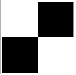
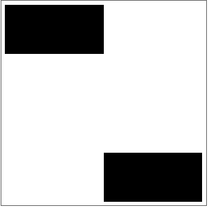
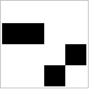
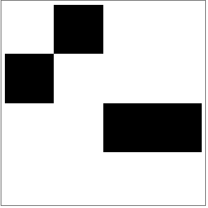
Here is a visualization of each of those matrices:
Out[]=
,
,
,
Computed Matrices
Computed Matrices
Swap switches two bits at positions s1 and s2.
Return reduces the number of bits, thereby creating a smaller subset of the original bits to use as an output.
For example, here are the expansion matrices increasing a systems wire count from 2 to 5
Gates to Matrices
Gates to Matrices
For example, here is how the NAND gate is represented when applied to the last two bits of a 4-bit system. The repeating NAND pattern can be seen on the least significant bits, and the diagonal identity pattern can be seen on the most significant bits.
Circuits Implementation
Circuits Implementation
Circuit Application
Circuit Application
A circuit is the composition of a set of gates applied to a set of wires. Because each gate is represented by a matrix, application of a gate is equivalent to multiplication of a state vector by a matrix. Because matrix multiplication is associative, all of the matrices of a circuit can be multiplied together into a single total circuit matrix. As most circuits require many more internal wires than input or output wires, a circuit matrix can be precomputed (which will take a relatively large amount of time) and then applied to one or more input state vectors (which will take a relatively small amount of time).
Finally, we can convert apply circuit to a logical function which can be displayed.
Here is the code that does this, first computing each matrix for each gate, then composing them by multiplication, then applying them to an input state, then creating a logic function from that:
Finally, we can convert apply circuit to a logical function which can be displayed.
Here is the code that does this, first computing each matrix for each gate, then composing them by multiplication, then applying them to an input state, then creating a logic function from that:
Example XOR Circuits
Example XOR Circuits
Now that we can create, apply, and visualize a circuit to an input, here are some circuits that perform the XOR gate using only the NAND gate:
As you can see, if we run these two circuits, we get the same truth table as XOR:
We can visualize these quantum circuits using the quantum circuit diagram from the Wolfram Quantum Framework paclet:
Here is a visualization of the matrices for each column of the smaller XOR circuit:
The first and last matrices are not square, because they setup and measure the state vector, respectively.
The interior gate matrices are mostly diagonally-shaped, because they are composed of only one gate matrix, but many identity matrices.
The first and last matrices are not square, because they setup and measure the state vector, respectively.
The interior gate matrices are mostly diagonally-shaped, because they are composed of only one gate matrix, but many identity matrices.
Here is the composition of all of the interior matrices:
And here is the final composition of all the matrices, which makes a matrix representation of XOR:
Universal Gates
Universal Gates
Definition
Definition
A set of gates is universal if a composition of it’s gates can be made equivalent to (or approximately equivalent to, within ε) any other possible gate.
Alternatively, in the matrix formulation of universality,
A set of universal gates can be formulated as the set of gates that comprises matrix decompositions to all other possible gates.
Below are formal mathematical definitions for the classical and quantum cases of universality:
Alternatively, in the matrix formulation of universality,
A set of universal gates can be formulated as the set of gates that comprises matrix decompositions to all other possible gates.
Below are formal mathematical definitions for the classical and quantum cases of universality:
Classical Definition
Classical Definition
Quantum Definition
Quantum Definition
Classical Universality
Classical Universality
Classical 21 Universality Proof
Classical 21 Universality Proof
Theorem
Theorem
A gate set containing at least one gate that satisfies each of the following properties is universal:
◼
G(a, a) = ¬a
◼
G(0, 0) + G(0, 1) + G(1, 0) + G(1, 1) is Odd
Lemma 1:
Lemma 1:
◼
In order to make a 21 NOT gate, a gate set must have a gate which satisfies the property G(a, a) = ¬a.
Corollary to Lemma 1:
Corollary to Lemma 1:
◼
Any 21 universal gate can replicate the behavior of the 11 NOT gate, as any input x can be copied to (x, x), onto which G can be applied, resulting in ¬x.
Lemma 2:
Lemma 2:
◼
For a 21 gate G to be universal, it must satisfy the property that G(a, ¬a) = G(¬a, a).
In order for a gate to be universal, it must be able to correlate two inputs together. That is, a gate G which can be written as G(p, q) = H(p) or G(p, q) = H(q), for some 11 gate H, cannot be universal. If G can be represented in such a way, then the condition holds that it is invariant under at least one input. Therefore, any gate G such that for all inputs p and q, either G(p, q) = G(¬p, q) or G(p, q) = G(p, ¬q) is not universal.
Let U be an oracle which is able to determine if a gate is universal. Implementing the condition just described into formal logic and simplifying:
(∀(p, q), G(p, q) = G(¬p, q) ∨ G(p, q) = G(p, ¬q)) ¬U(G)
U(G) ¬(∀(p, q), G(p, q) = G(¬p, q) ∨ G(p, q) = G(p, ¬q))
U(G) ∃(p, q), ¬(G(p, q) = G(¬p, q) ∨ G(p, q) = G(p, ¬q))
U(G) ∃(p, q), G(p, q) ≠ G(¬p, q) ∧ G(p, q) ≠ G(p, ¬q))
U(G) ∃(p, q), G(p, ¬q) ≠ G(p, q) ≠ G(¬p, q)
U(G) ∃(p, q), G(p, ¬q) = G(¬p, q)
For the sake of contradiction, when p = ¬q, (and thus q = ¬p), this statement simplifies to: U (G) ⇒ ∃(p, q), G(p, p) = G(¬p, ¬p) which, by Lemma 1, must be false. Therefore, when this condition for universality is met, p = q, and therefore: U (G) ⇒ G(p, ¬p) = G(¬p, p)
Proof:
Proof:
Results:
Results:
Out of all of the possible 21 gates
there exist only two gates which individually satisfy both of the properties given above:
Thus, these two gates, the NAND and NOR, respectively, are the only two gates which are individually universal.
Quantum Universality
Quantum Universality
Single Qubit Gates
Single Qubit Gates
Bloch Sphere Visualization
Bloch Sphere Visualization
Arbitrary Rotation Gates
Arbitrary Rotation Gates
In-Depth Solution Example
In-Depth Solution Example
Single-Qubit Gates
Single-Qubit Gates
Multi-Qubit Gates
Multi-Qubit Gates
Proof of Universality
Proof of Universality
Other Universal Sets
Other Universal Sets
Proof of CNOT
Proof of CNOT
Here are the complex matrices that make up my CNOT gate:
And here is the product of the individual matrices, compared to the actual CNOT:
The reason that they are different colors is because of global phase: the 00〉 state has a phase angle of π, so it has a phase coefficient of -1. Global phase can’t be measured or used for computation so it is not applicable to quantum computing and is usually discarded. Dividing by this global phase coefficient, it is proven that my CNOT and the conventional CNOT are equal:
Proof of T
Proof of T
Here are the complex matrices that make up my T gate:
And here is the product of the individual matrices, compared to the actual T:
Again, global phase is affecting the output. Correcting for that, these matrices are equivalent:
Proof of S
Proof of S
Here are the complex matrices that make up my S gate:
And here is the product of the column matrices, compared to the actual S:
Again, global phase is affecting the output. Correcting for that, these matrices are equivalent:
Proof of H
Proof of H
This gate applies the H using only gates from my universal set. Very similar to T and S, it relies on transforming a qubit to the 1〉 state, then using the controlled z rotation to implement the actual logic.
Here are the complex matrices that make up my H gate:
And here is the product of the individual matrices, compared to the actual H:
Again, global phase is affecting the output. Correcting for that, these matrices are equivalent:
Note on 11 vs 22
Note on 11 vs 22
Example: Superdense Coding
Example: Superdense Coding
Here is an example of a real quantum circuit implemented only in terms of my universal gate set:
It implements the superdense coding protocol, which allows two classical bits of information to be transferred with only one qubit.
It implements the superdense coding protocol, which allows two classical bits of information to be transferred with only one qubit.
Results
Results
Future Research
Future Research
Acknowledgements
Acknowledgements
I would like to thank my mentor, Dugan “The Goat” Hammock, for his valuable explanation, instruction, and feedback throughout my project, as well as Daniele Ceravolo for his help with the mathematics. I appreciate all the other people who took interest in and talked through my project with me, including Aisha, Ritvik, Gregory, Bertie, Maximilian, Mary, and all the others. Finally, I would like to thank all the other students, TAs, mentors, and staff who have made my experience at this program absolutely incredible.
Bibliography
Bibliography
◼
Barenco, A., Bennett, C. H., Cleve, R., DiVincenzo, D. P., Margolus, N., Shor, P., ... & Weinfurter, H. (1995). Elementary gates for quantum computation. Physical review A, 52(5), 3457.
◼
Garcia, S. (2018, April 30). L0 Norm, L1 Norm, L2 Norm & L-Infinity Norm. Medium. Retrieved July 10, 2024, from https://montjoile.medium.com/l0-norm-l1-norm-l2-norm-l-infinity-norm-7a7d18a4f40c
◼
Nielsen, M. A., & Chuang, I. L. (2023). Quantum computation and quantum information (10th ed.). Cambridge University Press.
◼
Rotation operators. (n.d.). Quantum Inspire. Retrieved July 10, 2024, from https://www.quantum-inspire.com/kbase/rotation-operators/
◼
Shi, Y. (2002). Both Toffoli and Controlled-NOT need little help to do universal quantum computation. https://arxiv.org/abs/quant-ph/0205115
◼
Universal set of quantum gates [Lecture notes]. (n.d.). SAIFR-ICTP. Retrieved July 10, 2024, from https://www.ictp-saifr.org/wp-content/uploads/2022/11/ICTP_SAIFR_D1-L2.pdf
◼
Zalcman, A. (2021, April 21). Does anyone know the list of all known universal sets of quantum gates? [Online forum post]. Quantum Computing Stack Exchange. https://quantumcomputing.stackexchange.com/questions/17173/ does-anyone-know-the-list-of-all-known-universal-sets-of-quantum-gates
Footnotes
Footnotes
CITE THIS NOTEBOOK
CITE THIS NOTEBOOK
Minimal universal classical and quantum gates
by Christopher Gilbert
Wolfram Community, STAFF PICKS, July 11, 2024
https://community.wolfram.com/groups/-/m/t/3214252
by Christopher Gilbert
Wolfram Community, STAFF PICKS, July 11, 2024
https://community.wolfram.com/groups/-/m/t/3214252