The racing line is the fastest theoretical route through a corner, and drivers practice for hours to perfect it to ensure the lowest possible lap times. However, as racing has become increasingly more complicated over the decades, the racing line has become as optimized as possible. However, for the everyday racer, there are no such machines that would help them improve their times on their local tracks. Therefore, this paper is about developing an optimal racing line that would take you around a 2D track in the quickest possible time, using segments of Euler spirals as my racing lines. The paper uses single and double 2D corner segments of race tracks and the Euler spiral to come up with an optimal route to go through the turns.
Getting and Segmenting an Euler Spiral
Getting and Segmenting an Euler Spiral
The Euler spiral is a good choice as a racing line because of its consistent, linear change in curvature that a racing line should also have. Therefore, the smooth curve that the Euler spiral provides should be able to simulate the optimal racing line's route. Now, the question is how to use it to represent the racing line of a corner.
Gets Euler spiral.
In[]:=
euler2[t_]:= FresnelC t, FresnelS t
π
2
2
π
π
2
2
π
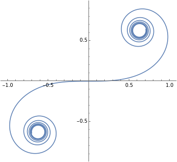
Plots the Euler spiral in a 2D plane.
In[]:=
ParametricPlot[euler2[t],{t,-2*Pi,2*Pi}]
Out[]=
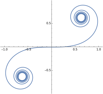
Cuts between two chosen points in the Euler spiral using manipulate to control where you want to cut.
In[]:=
Manipulate[ParametricPlot[euler2[t],{t,v,u}],{v,2Pi,-2Pi},{u,-2Pi,2Pi},SaveDefinitions->True]
Out[]=


Plotting Single Turn Race Track Models
Plotting Single Turn Race Track Models
Getting potential uniform models that would be used for developing the correct racing lines depending on the angle of the turn while also having similar lengths.
Makes a 90 degree right turn as a model for my racing line.
In[]:=
uniform90RightTurn=ShowGraphicsCircle{1,0},0.75,0,,Circle{1,0},0.25,0,,Graphics[{Line[{{1.25,0},{1.25,-1}}],Line[{{1.75,0},{1.75,-1}}]}],Graphics[{Line[{{1,0.25},{-1.4,0.25}}],Line[{{1,0.75},{-1.4,0.75}}]}]
Pi
2
Pi
2
Out[]=
Makes a 180 degree turn or hairpin as a model for my racing line.
In[]:=
uniformHairpintrack=Show[{Graphics[{Circle[{1,0},0.75,{0,Pi}],Circle[{1,0},0.25,{0,Pi}]}],Graphics[{Line[{{1.25,0},{1.25,-1}}],Line[{{1.75,0},{1.75,-1}}],Line[{{0.75,0},{0.75,-1.5}}],Line[{{0.25,0},{0.25,-1.5}}]}]}]
Out[]=
Makes a 45 degree left turn as a model for my racing line.
In[]:=
uniform45LeftTurn=ShowGraphicsLine[{{1.25,0},{1.25,-2.6}}],Line[{{1.75,0},{1.75,-2.6}}],Circle{1,0},0.75,0,,Circle{0.5,0},0.75,0,,Line[{{1.53,0.53},{0.93,1.13}}],Line[{{1.03,0.53},{0.63,0.93}}]
Pi
4
Pi
4
Out[]=
Get Racing Line for Chosen Turns
Get Racing Line for Chosen Turns
Finally, getting the part of the Euler spiral with the angle of the turn in question.
A function that acquires a section of the Euler spiral that fits the angle of a corner in a race track. Input the angle, in degrees, of the turn into the function “findRacingLine” and the output will plot the portion of the Euler spiral with said inputted angle.
Racing line for a 45 degree turn.
Racing line for a 90 degree turn.
Racing line for a 180 degree turn.
Examples of different curvatures and their racing lines that are segmented from the Euler spiral.
Putting a Racing Line into a Model Turn
Putting a Racing Line into a Model Turn
The idea behind this segment is the placement of the racing line in the race track.
This function acquires the angle of the turn, the x and y coordinates of the racing line, the scale of the racing line, if you need to plot the racing line with a negative x or y value, and if you want to reflect the racing line to fit it properly in the racing track.
This is one successful implementation of the racing line of a 180-degree turn into the track itself. I did not just randomly guess and check the values of each variable. I first switched the negative and reflecting values to make sure the racing line follows a direction that looks relatively like the turn in question. Then I used a manipulate function to put the start of the racing line on the outside line of the exit point of the turn. Next, I would change the scale of the racing line to make sure it fits in between the track limits so the car in question doesn't run off the track. At last, I would change the y-value, in this case, to make it just barely hit the late apex of the turn.
The reason the late apex is chosen in this single-corner example is that it is preferred in turns that are right before a straight section of the track because you would be able to carry on the acceleration quicker. The chosen apex depends on the proximity of the next turn and if the racing lines would overlap with each other.
The reason the late apex is chosen in this single-corner example is that it is preferred in turns that are right before a straight section of the track because you would be able to carry on the acceleration quicker. The chosen apex depends on the proximity of the next turn and if the racing lines would overlap with each other.
Play with the manipulate function yourself~!
Another example but with a 90 degree turn. The entry point is from the right.
Play with the manipulate function of the 90 degree turn yourself~!
Another example but with a 45 degree turn. The entry point is from below.
Play with the manipulate function yourself~!
Plotting Two Turn Race Track Models
Plotting Two Turn Race Track Models
Makes a two 90 degree left turn model.
Makes a 90 degree left turn followed by a 90 degree right turn model.
Makes a two 90 degree left turn model that are closer to each other.
Putting Two Racing Lines into Two Combined Model Turns
Putting Two Racing Lines into Two Combined Model Turns
The idea behind this section of the research paper is that the last turn before the exit point should always be prioritized with a late apex racing line while sacrificing the efficiency of the previous corners. This is because the last line will always need the most time for acceleration because of the straight that follows. Therefore, matching up the racing line of previous turns to the racing line of the final corner would theoretically make the most optimal racing line.
A new function for finding the racing line if the multiple racing lines will overlap with each other. The new variable “start” would cut off a certain part of the racing line to make sure it fits.
The two optimal racing lines for each of these corners don’t overlap with each other, so there is no need to change the first racing line to match up with the last corner.
The entry point is from the right.
The entry point is from the right.
https://www.youtube.com/clip/Ugkx5POBraFYUI2S3LTqf1SuimvuwORMHXPU
A similar racing line taken by McLaren drive Lando Norris during the 2021 Russian Grand Prix on corners 18 and 19.
A similar racing line taken by McLaren drive Lando Norris during the 2021 Russian Grand Prix on corners 18 and 19.
The two optimal racing lines for these two corners will overlap, so you need to change the racing line for the entry point to match the optimal racing line for the exit corner.
As you can see, the racing line for the entry point is nowhere near optimal, but it sets up the exit that will carry the acceleration to the straight.
As you can see, the racing line for the entry point is nowhere near optimal, but it sets up the exit that will carry the acceleration to the straight.
https://www.youtube.com/clip/Ugkx3apxMWXisuHO9CGeoo8NYxG5QvTVrzwj
A similar but less extreme example of the racing line by Red Bull driver Max Verstappen during the 2021 Abu Dhabi Grand Prix on corners 6 and 7.
A similar but less extreme example of the racing line by Red Bull driver Max Verstappen during the 2021 Abu Dhabi Grand Prix on corners 6 and 7.
Two corners that are similar to the first example, but both of the racing lines do overlap. Therefore, it is necessary to adjust the entry corner’s racing line to match with the exit turn’s late apex racing line. However, after doing that, the exit corner’s racing line still overlaps with the entry point’s, so we have to cut off small sections of the end of each line to make sure they connect with each other.
https://youtube.com/clip/UgkxLqySftqA7eMOp5W0w_LV7dNXFykDMdVU
A slightly different example of the racing line by Red Bull driver Max Verstappen during the 2023 Bahrain Grand Prix on corners 9 and 10.
A slightly different example of the racing line by Red Bull driver Max Verstappen during the 2023 Bahrain Grand Prix on corners 9 and 10.
Conclusion & Future Works
Conclusion & Future Works
Coming into this project with only knowledge of racing and minimum knowledge of physics in general, the project was a good learning and coding experience. I spent most of my time during the beginning of the project researching Euler spirals and how to get an optimal racing line, but after getting the results of my research, I'll be able to do much more with my results that I couldn't get to during my time at the camp. First, I would make a function that would automatically place the racing line into any said turn without any of the manual inputs I used earlier. Next, I would implement any indications of braking and acceleration using the physical limitations of the car the user inputs: acceleration and braking capabilities, top speed, mass, grip, etc. Then, I would animate a car model into the track that would follow the racing line. Finally, I would move on and advance the project into a 3D plane to be able to get a much more realistic racing line that takes into consideration the banking angles, elevation, and much more.
References
References
"Lando Norris' Pole Lap | 2021 Russian Grand Prix | Pirelli ." YouTube, 25 Sept . 2021, www.youtube.com/watch?v=tib5NDmyn0M&ab_channel=FORMULA1 .
“Max Verstappen’s Pole Lap | 2021 Abu Dhabi Grand Prix | Pirelli.” YouTube, 11 Dec. 2021, www.youtube.com/watch?v=S_jdcUVtaTU&ab_channel=FORMULA1.
“Max Verstappen’s Pole Lap | 2023 Bahrain Grand Prix | Pirelli.” YouTube, 4 Mar. 2023, www.youtube.com/watch?v=RMpWukELqCc&ab_channel=FORMULA1.
Xiong, Ying. Massachusetts Institute of Technology, 2010, dspace.mit.edu/bitstream/handle/1721.1/64669/706825301-MIT.pdf.
“Different Corners, Different Techniques: Optimise Every Turn.” Driver61, 13 Jan. 2022, driver61.com/uni/different-corner-technique/.
Acknowledgements
Acknowledgements
CITE THIS NOTEBOOK
CITE THIS NOTEBOOK
Optimizing racing lines
by Isaiah Yang
Wolfram Community, STAFF PICKS, July 13, 2023
https://community.wolfram.com/groups/-/m/t/2963938
by Isaiah Yang
Wolfram Community, STAFF PICKS, July 13, 2023
https://community.wolfram.com/groups/-/m/t/2963938