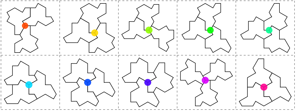
In the previous discussion, a list of vertex configurations was derived. However, some of them with beautiful rotation symmetry do not appear in the big cluster. In fact, here we try to prove they are invalid, which means they cannot appear in the cluster which covers the whole plane, or it is impossible for a cluster to cover the whole plane when they have this kind of configurations.
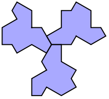
The most important three conclusions are 1/3+1/3+1/3, 1/4+1/4+1/4+1/4 and “T”, which is 1/4+1/4+edge. Here they are:
| ||
| ||
|

Here we prove the last two of 1/3 Vertex Configuration and 1st, 3nd, 4th configurations of 1/4 Vertex Configuration are invalid.
The strategy is, once a configuration is proven invalid, delete it from the theorem list. The code is doing same thing but opposite way - add all cases need to prove at first, once a case is proven then only add the rest.
So, the order does matter. The 11,11,11 Comes first. The following are detailed proving processes. If you want to see something more clearly and directly, read Summary directly, where it is easy to see the whole process clearly.
Prove invalidity of (11,11,11)
Prove invalidity of (11,11,11)
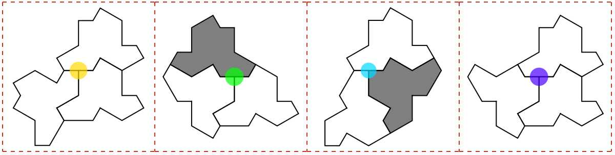
Prove the invalidity of
Prove the invalidity of
Prove the invalidity of
Prove the invalidity of
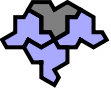
Prove the invalidity of
Prove the invalidity of
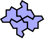
Prove the invalidity of (5,5,5)
Prove the invalidity of (5,5,5)
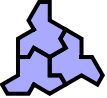
Prove Summary
Prove Summary
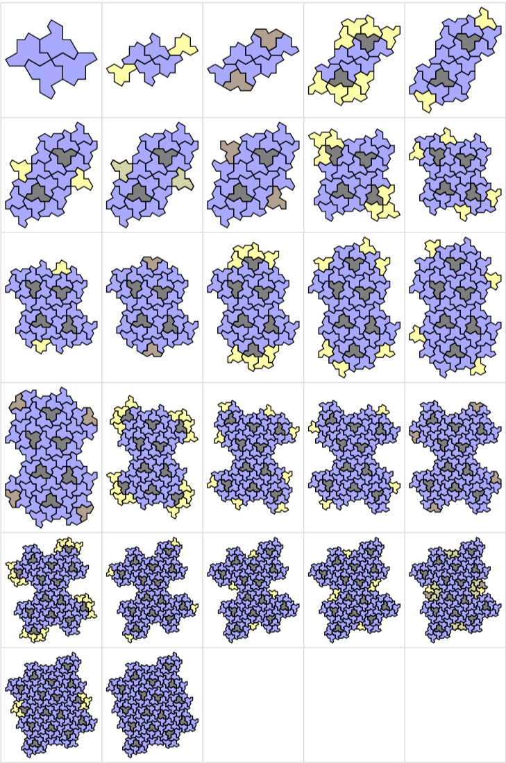
In order to compare with the former state, all new tiles of the following state will be colored differently ( yellow for unreflected new hat, brown for reflected)
In[]:=
Options[drawGrid]=Options[Grid];drawGrid[data_,part_:5,opt:OptionsPattern[]]:=Grid[Partition[MapThread[show[#2,#1,EdgeThick->False]&,{Prepend[#,#[[1]]]&[data],Join[{{}},Complement[#2,#1]&@@@Partition[data,2,1],{{}}]}],UpTo[part]],opt]
1.
1.
In[]:=
drawGrid,5,Frame->All,FrameStyle->LightGray,ItemSize->{8,6}
Out[]=
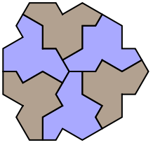
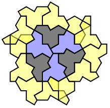
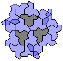
2.
2.
In[]:=
drawGrid,5,Frame->All,FrameStyle->LightGray,ItemSize->{8,6}
Out[]=
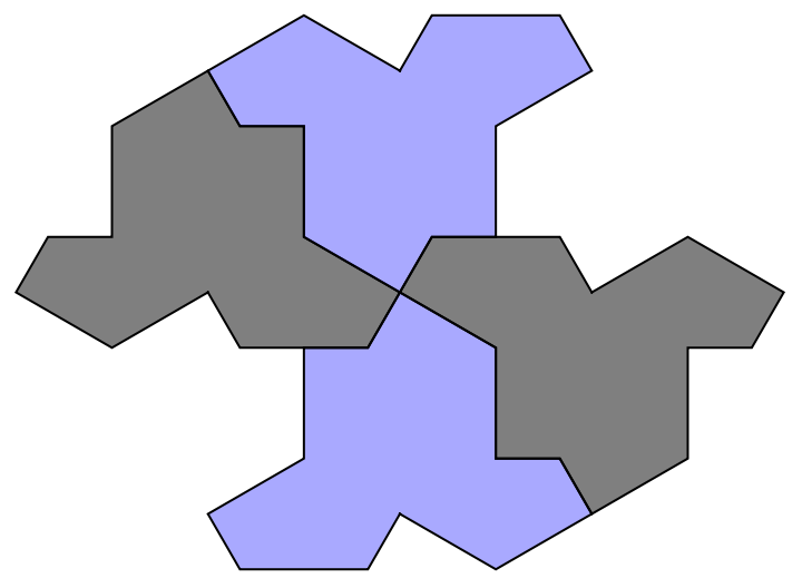
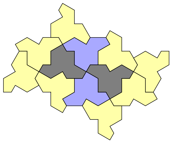
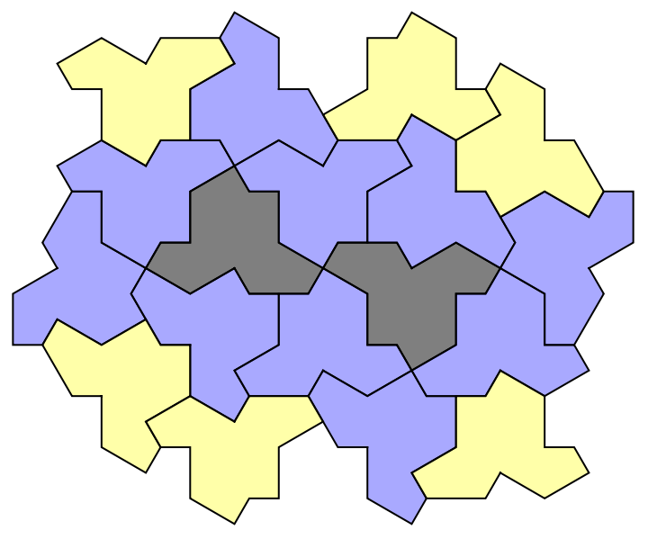
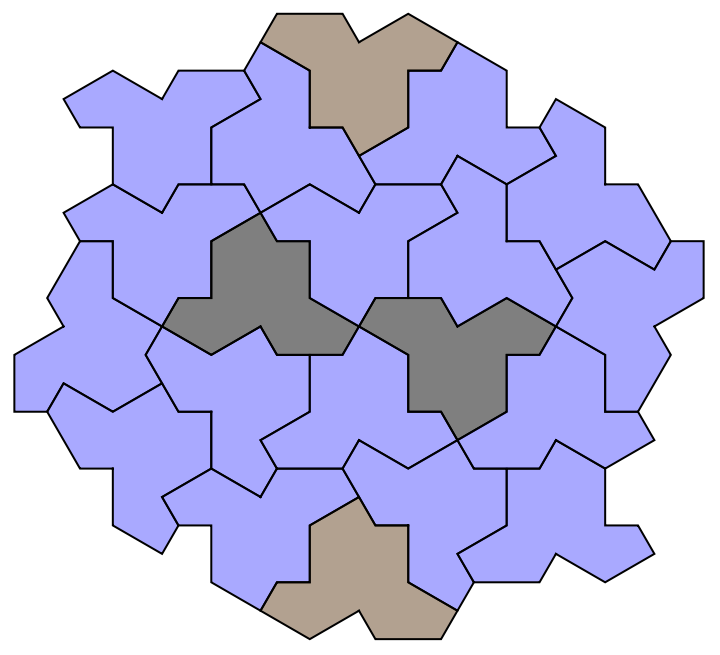
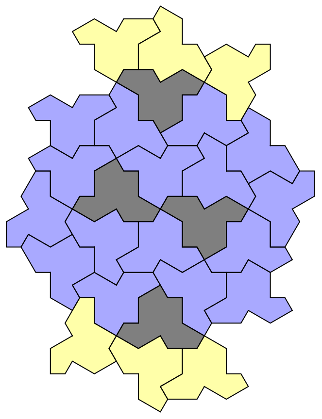
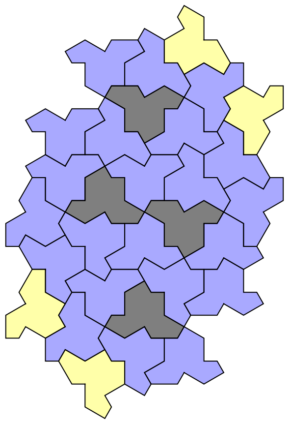
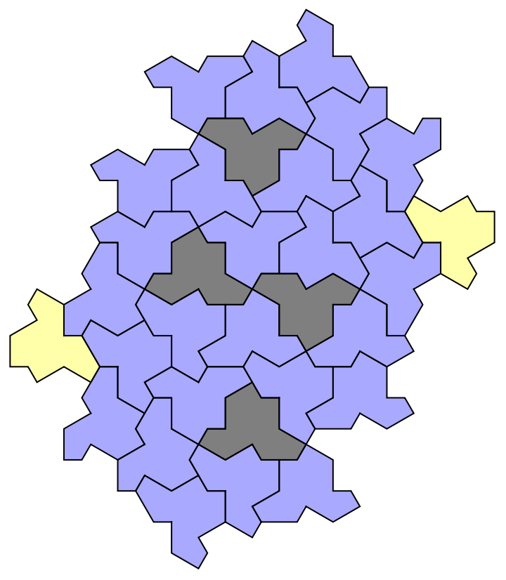
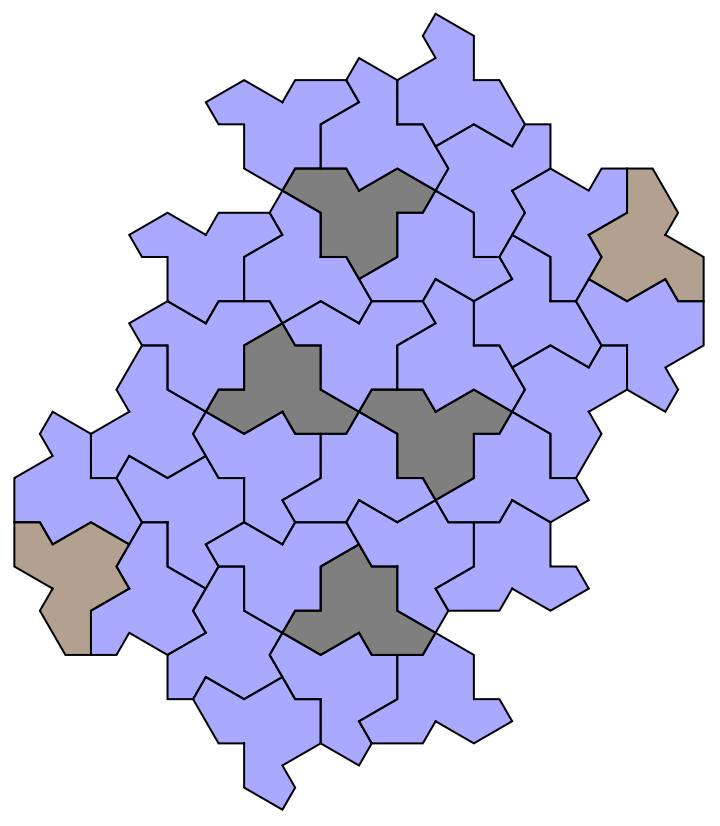
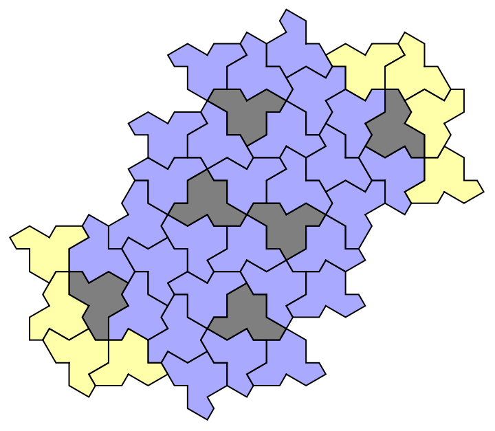
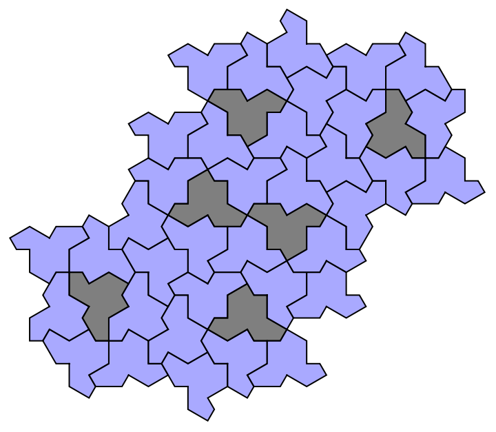
3.
3.
In[]:=
drawGrid,6,ItemSize->{6,5},Frame->All,FrameStyle->LightGray
Out[]=
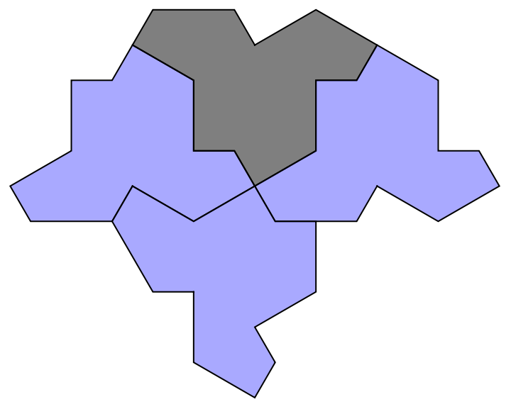
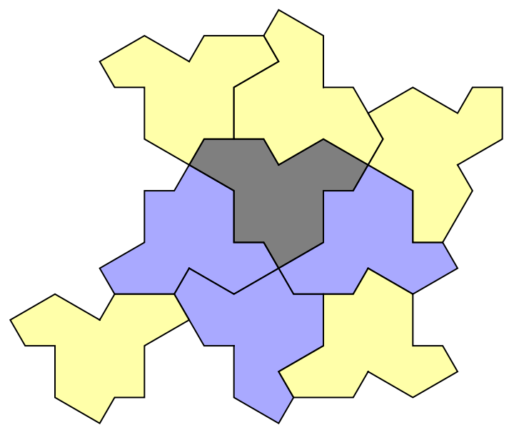
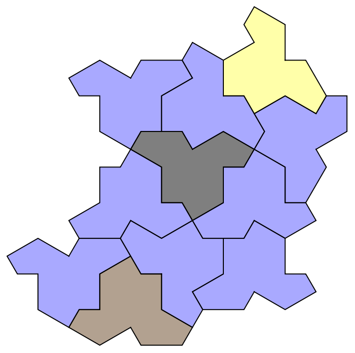
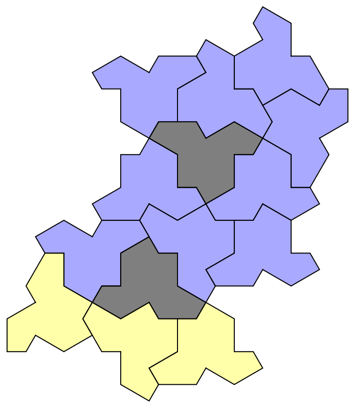
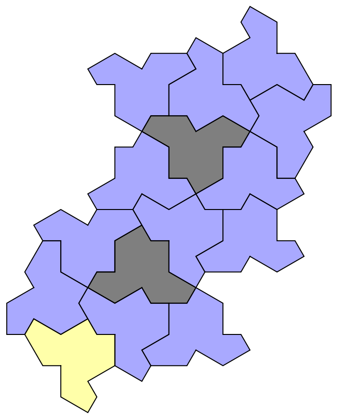
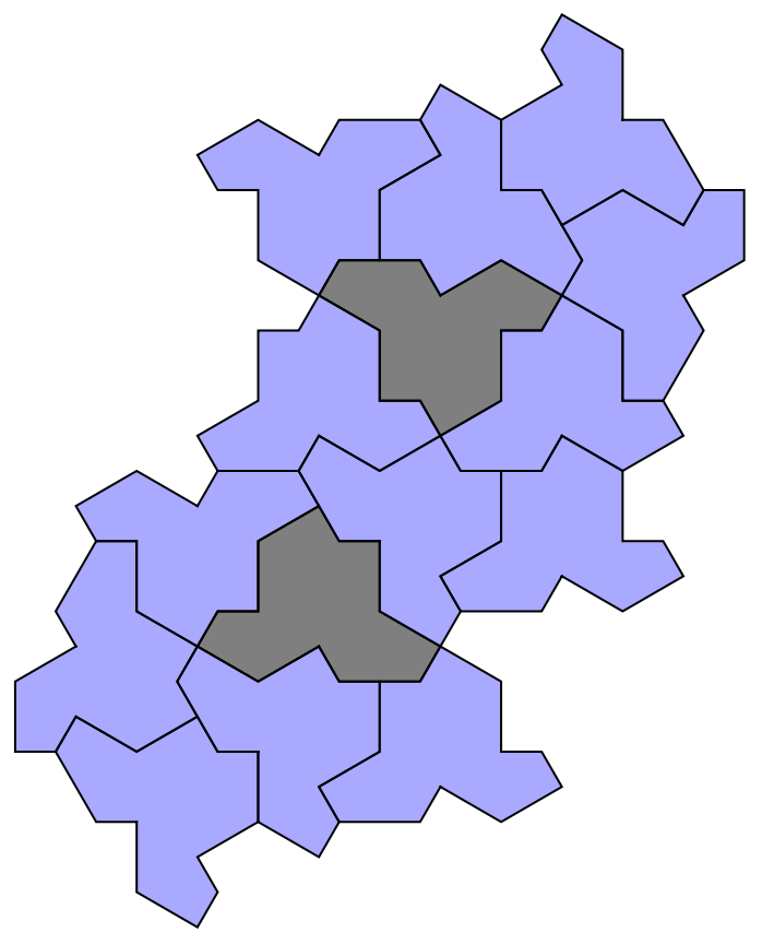
4.
4.
◼
Main branch
In[]:=
drawGrid,5,ItemSize->{8,6},Frame->All,FrameStyle->LightGray
Out[]=
◼
Branch 1
This is branch 1, the first state is the same as the last state of main branch. It ends up with two symmetric gaps, which are highlighted with yellow in the second to the last graph.
◼
Branch 2
This is branch 2, the first state is the same as the last state of main branch. It ends up with two symmetric gaps, which are highlighted with yellow in the second to the last graph.
Branch 1 and Branch 2 end up with same problem but different position.
5.
5.
It ends up with three holes near to the boundary.
Conclusion
Conclusion
After proving these invalid cases, the valid cases are:
Because all of them appear in the super-tile, which is used to generator bigger super-tile to cover the whole plane in the original paper, this result is the least set of vertex configurations for 1/3, 1/4 and “T”.
CITE THIS NOTEBOOK
CITE THIS NOTEBOOK
Hat tiling: vertex configurations further reduction
by Bowen Ping
Wolfram Community, STAFF PICKS, July 14, 2023
https://community.wolfram.com/groups/-/m/t/2967510
by Bowen Ping
Wolfram Community, STAFF PICKS, July 14, 2023
https://community.wolfram.com/groups/-/m/t/2967510