Determine the Type of Stress in Each Member of a Truss
Determine the Type of Stress in Each Member of a Truss


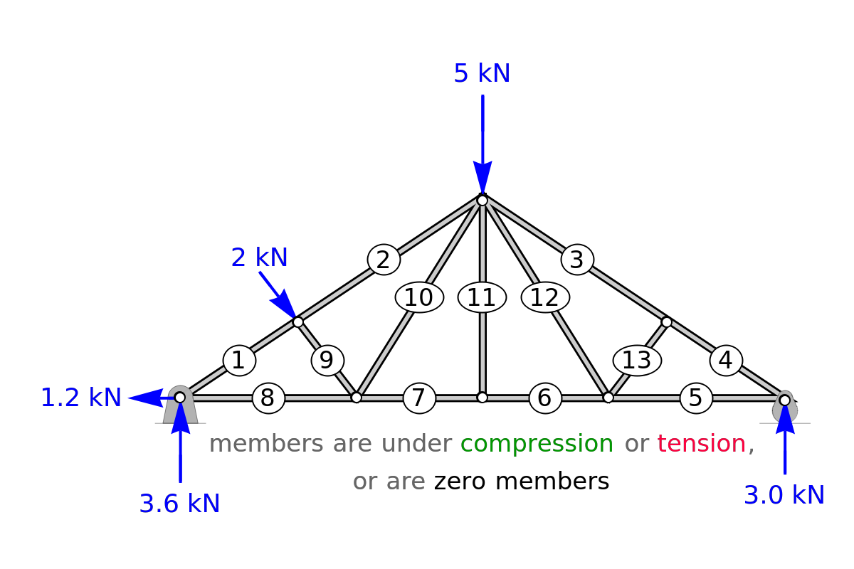
Based on your understanding of force balances, guess whether a selected member of the truss is under compression, under tension, or is a zero member. Set the diagonal and vertical point loads with sliders. The reaction forces (blue) are calculated and displayed on the truss. Select "guess force on a member", use the popup menu "select a member" (from 1 to 13), and then select "compression", "tension" or "zero member" from the next popup menu. Check the "check answer" box to see if your guess is correct.
Members under compression are green with arrows pointing outward, members under tension are red with arrows pointing inward, and zero members are black. A zero member is under neither tension nor compression; it has a force of 0 kN. Zero members act as additional support for the structure. Select "solved truss" to see the numerical values of all members.
Details
Details
First, solve for the reaction forces. The sum of the forces in the direction, moment about joint and the sum of the forces in the direction are:
x
A
y
∑=0=+cos
F
x
R
A,x
F
B
θ
1
∑=0=z+(+)-2(+)
M
A
F
B
w
1
w
2
F
C
w
1
w
2
R
E
∑=0=-sin-+
F
y
R
A,y
F
B
θ
1
F
C
R
E
where
w
1
w
2
θ
1
-1
tan
h
1
0.33
w
2
2
z
2
h
1
2
(0.67)
w
2
h
1
h
2
The method of joints is used to solve the forces in the members of the truss. Force balances are done around individual joints. Follow the order of the balances indicated below to obtain a solution. Calculations assume we can determine which members are under compression and tension before doing the calculations, but this is not necessary. See the labeled truss in Figure 1 below.
Joint A: , , where =.
∑=0=-sin+
F
y
F
1
θ
2
R
A,y
∑=0=-cos++
F
x
F
1
θ
2
F
8
R
A,x
θ
2
-1
tan
h
1
0.67
w
2
Joint B: , .
∑=0=-
F
y
F
1
F
2
∑=0=-
F
x
F
B
F
9
Joint H: , , where =+.
∑=0=-sin+sin
F
y
F
9
θ
1
F
10
θ
3
∑=0=-+cos+cos
F
x
F
7
F
8
F
9
θ
1
F
10
θ
3
θ
3
-1
tan
h
1
h
2
w
1
Joint G: , .
∑=0=
F
y
F
11
∑=0=-
F
x
F
6
F
7
Joint E: , .
∑=0=-sin+
F
y
F
4
θ
2
R
E
∑=0=cos-
F
x
F
4
θ
2
F
5
Joint D: , .
∑=0=
F
y
F
13
∑=0=-
F
x
F
3
F
4
Joint F: .
∑=0=sin+sin
F
y
F
12
θ
3
F
13
θ
1
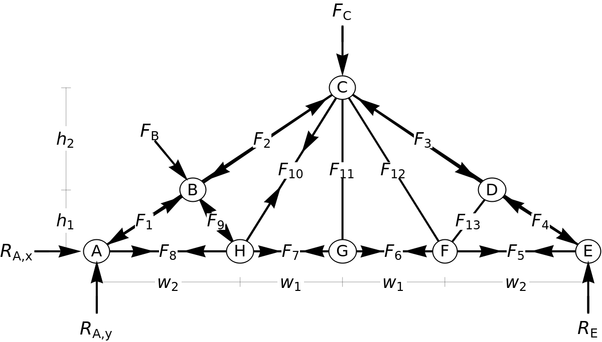
Figure 1.
Permanent Citation
Permanent Citation
Rachael L. Baumann, John L. Falconer
"Determine the Type of Stress in Each Member of a Truss"
http://demonstrations.wolfram.com/DetermineTheTypeOfStressInEachMemberOfATruss/
Wolfram Demonstrations Project
Published: September 8, 2017