Pulse Width Modulation Principle
Pulse Width Modulation Principle


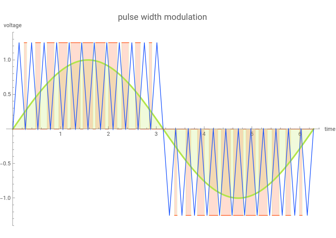
This Demonstration generates a graphical representation of pulse width modulation (PWM) used for variable frequency AC motor drives (VFDs). The carrier frequency signal is illustrated in blue while the reference signal (sine wave) is green.
Details
Details
You can change the relative frequency of the carrier signal to observe the change in pulse width relative to the reference signal. You can also turn off the carrier frequency triangle plot to see the other signals more clearly. In addition, you can change the magnitude of the reference signal and add the third harmonic distortion.
The PWM technique can reproduce almost any wave form, not just a sine wave. PWM allows a switching device to dissipate relatively low power while it is either saturated (full on) or in cut-off.
Principles referenced from: D. Hart, Introduction To Power Electronics, Upper Saddle River, NJ: Prentice Hall, 1997.
External Links
External Links
Permanent Citation
Permanent Citation
Harley H. Hartman
"Pulse Width Modulation Principle"
http://demonstrations.wolfram.com/PulseWidthModulationPrinciple/
Wolfram Demonstrations Project
Published: January 9, 2008