Configuration Space for Four-Bar Linkage
Configuration Space for Four-Bar Linkage


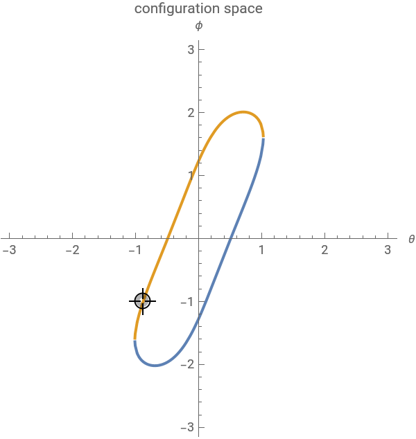
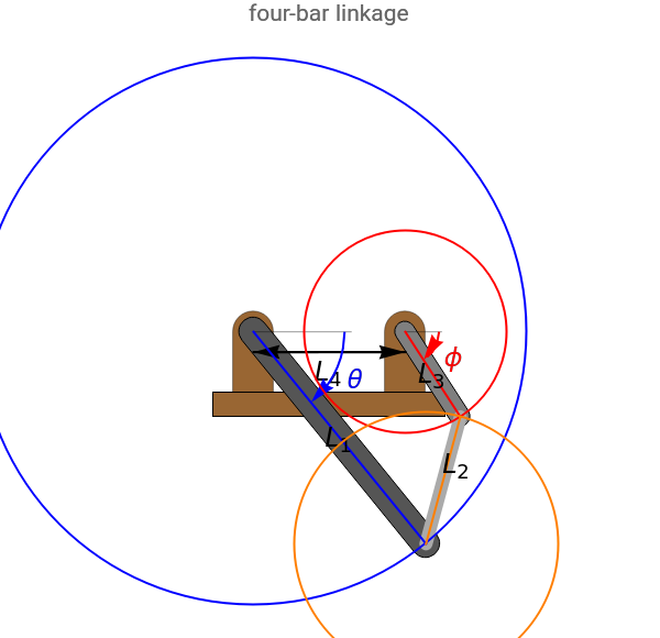
A planar four-bar linkage has four joints, so its configuration is described by four numbers. However, because the linkage is a closed chain, the resulting constraints make most configurations unattainable. The linkage's configuration space is a one-dimensional curve embedded in a four-dimensional space. The plot at left projects the configuration space onto the joint angles of the first and third links. You can drag the locator to explore the set of reachable configurations. Because and are angles, this configuration space wraps around from to . If any link is greater than the sum of the other three links, no valid configurations exist.
(θ,ϕ)
θ
ϕ
-π
π
Details
Details
In this Demonstration, links 1 and 3 are connected to the ground plane and are separated by a distance that can be adjusted by the slider "separation ()". The other three link lengths are set by the interval slider.
L
4
The four-bar linkage has four links, which are connected in a closed chain. The four-bar linkage is therefore a parallel mechanism. Grübler's formula states that the number of degrees of freedom of a planar mechanism is given by
DOF=3(N-1-J)+
J
∑
i=1
f
i
In this Demonstration, is the number of degrees of freedom, is the number of links, is the number of joints, and =1 is the number of degrees of freedom provided by joint . The of the four-bar linkage is therefore .
DOF
N=4
J=4
f
i
i
DOF
3(4-1-4)+4=1
The kinematic loop constraint equations for the four-bar linkage are given in[1] as:
ϕ=arctan(α,β)±arcos+
γ
2
α
2
β
where
α=2-2cosθ
L
3
L
4
L
1
L
3
β=-2sinθ
L
1
L
3
γ=---+2cosθ
2
L
2
2
L
4
2
L
3
2
L
1
L
1
L
4
Here , and are the lengths of the three links and is the separation distance of links 1 and 3. These equations can be found using the law of cosines. The sign in the expression for gives two solutions. The more positive solution of is drawn with an orange line, and the more negative solution with a blue line.
L
1
L
2
L
3
L
4
±
ϕ
ϕ
Depending on the link lengths chosen, the configuration space curve may have bifurcation points where branches of the curve meet. Snapshot 1 with link lengths has bifurcations at , , and . Snapshot 2 has no bifurcations, and Snapshot 3 with link lengths has a bifurcation at .
[1,1,0.5,0.5]
(0,π)
(0,-π)
(π,π)
(-π,-π)
[0.9,1.2,0.5,0.8]
(0,0)
Vertical lines in the configuration space plot are spurious.
References
References
[1] K. M. Lynch and F. C. Park, Modern Robotics: Mechanics, Planning, and Control, New York: Cambridge University Press, 2017.
External Links
External Links
Permanent Citation
Permanent Citation
Aaron T. Becker, Shiva Shahrokhi
"Configuration Space for Four-Bar Linkage"
http://demonstrations.wolfram.com/ConfigurationSpaceForFourBarLinkage/
Wolfram Demonstrations Project
Published: January 11, 2018