This is part of live presentation series called Mathematical Games in which we explore a variety of games and puzzles using Wolfram Language. In this episode, we explore the mathematical games and puzzles involving linkages.
demonstrations.wolfram.com
demonstrations.wolfram.com
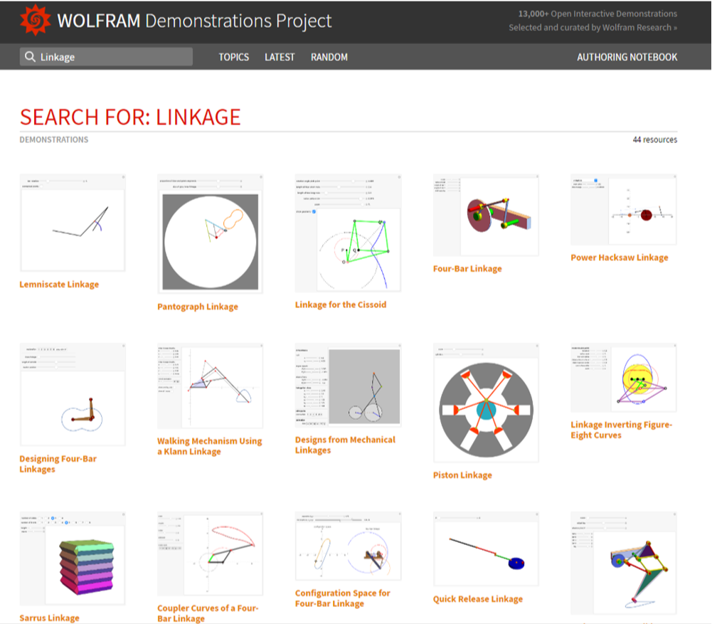
Many Demonstrations involve linkages.
New Highest Prime and Highest Perfect Number (Book 7)
New Highest Prime and Highest Perfect Number (Book 7)
1362798412-1 is prime! 88169432750383326555...55076706219486871551(1362798412-1)(136279841-12) is perfect 38869244357621839661...38972750732330008576
136279841
2
136279841
2
136279841-1
2
In[]:=
N[(-1)(),30]
136279841
2
136279841-1
2
Out[]=
3.88692443576218396619716597046×
82048639
10
In[]:=
(PowerMod[2,136279841,10^80]-1)PowerMod[2,136279840,10^80]
Out[]=
4618537982188607020630425077558932204698666322649571062608970366309887781261016262418262416018804895702555316111949805495520297305681205442638972750732330008576
In[]:=
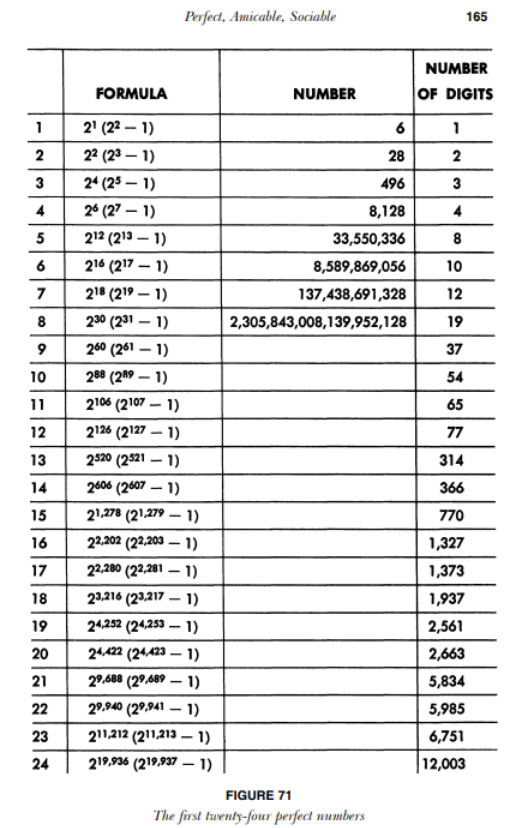
perfect8=2^30(2^31-1);{perfect8,Total[Drop[Divisors[perfect8],-1]]}
Out[]=
{2305843008139952128,2305843008139952128}
In[]:=
perfect12=2^126(2^127-1);{perfect12,Total[Drop[Divisors[perfect12],-1]]}
Out[]=
{14474011154664524427946373126085988481573677491474835889066354349131199152128,14474011154664524427946373126085988481573677491474835889066354349131199152128}
What is a linkage?
What is a linkage?
A linkage is usually a system of connected rigid bars with fixed or connected endpoints.
A circle can be made with a linkage. Fix one end, find the points covered by the other end.
In[]:=
Graphics[{Thick,Line[{{0,0},{3,4}/5}],Cyan,Circle[{0,0},1]}]
Out[]=
Kempe’s Linkage (Gardner)
Kempe’s Linkage (Gardner)
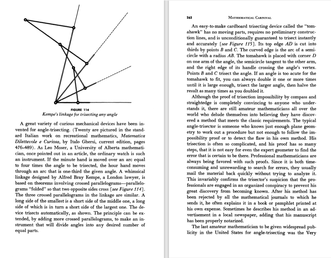
The Kempe linkage can trisect an angle. (Click the image to enlarge)
Kempe’s Angle Trisector (Izidor Hafner)
Kempe’s Angle Trisector (Izidor Hafner)
This Demonstration models Kempe’s angle trisector.
Peaucellier’s and Hart’s Inversor (Izidor Hafner, Erik D. Demaine and Joseph O’Rourke)
Peaucellier’s and Hart’s Inversor (Izidor Hafner, Erik D. Demaine and Joseph O’Rourke)
Rotary to Linear Motion (Sándor Kabai)
Rotary to Linear Motion (Sándor Kabai)
Rotary motion can be converted to linear motion using this mechanical combination. This drive mechanism is often used in machine tools, such as shapers, for example. You can harmonize the many possible parameters according to the needs of the actual application.
Pump Jack (Sándor Kabai)
Pump Jack (Sándor Kabai)
One of the bars of a four-bar linkage is extended beyond its hinge to model the operation of a pump jack. Pump jacks are used to pump oil out of the ground.
Pantograph Linkage (Michael Schreiber)
Pantograph Linkage (Michael Schreiber)
This linkage was invented by Christoph Scheiner in 1630. It makes a scaled copy of a given figure. The proportions of the outer and inner segments modify the size and shape of the copy. Drag the locator around the orange figure to make the red dot trace out the pink copy.
Nuremberg Scissors (Sándor Kabai and Szaniszló Bérczi)
Nuremberg Scissors (Sándor Kabai and Szaniszló Bérczi)
Bars are hinged together in the middle and more scissors are added to form an extendable mechanism. A device designed with this principle was used on the Surveyor Moon landers to scoop up soil for testing.
Linkage for the Cissoid (Claude Fabre)
Linkage for the Cissoid (Claude Fabre)
Lemniscate Linkage (Ed Pegg Jr)
Lemniscate Linkage (Ed Pegg Jr)
The midpoint of the middle bar of a 3-bar linkage traces out a curve known as a lemniscate. It is interesting to note that a lemniscate is a cross section of a torus.
Four-Bar Linkage (Sándor Kabai)
Four-Bar Linkage (Sándor Kabai)
Four bars are connected in a loop with hinged joints to form a four-bar linkage. In this Demonstration three of the bars are cylindrical and the fourth is a block in which shafts are inserted to support two of the hinges. One hinge can be rotated around a shaft, while another hinge moves along part of a circle back and forth around the other shaft.
Desk Lamp (Sándor Kabai)
Desk Lamp (Sándor Kabai)
A lamp is mounted on a support consisting of two four-bar linkages. The orientation of lamp remains constant while tilting and turning the linkage, although the lamp can be adjusted separately. The whole support can be rotated around a vertical fulcrum, which protrudes from a base.
Chebyshev’s Lambda Mechanism (Nikita Panyunin and Nikolai Andreev)
Chebyshev’s Lambda Mechanism (Nikita Panyunin and Nikolai Andreev)
Chebyshev saw the resemblance of the blue joint trajectory to the trajectory of a horse’s hoof. He attached legs to four such lambda mechanisms to get the first walking mechanism, which he called the plantigrade machine. To see a 3D model, go to Mechanisms by Tchebyshev.
(Also known as Tchebichef, Tchebychev, Tchebycheff, Tschebyschev, Tschebyschef, Tschebyscheff, Čebyčev, Čebyšev, Chebysheff, Chebychov, Chebyshov)
Circular Scissors Lift (Sándor Kabai)
Circular Scissors Lift (Sándor Kabai)
Two bars are attached at their center with a hinge to form scissors. Three such scissors are arranged to form the first story, held firmly in place for stability. More stories are stacked to make a framework. To extend or retract the structure, the bottom three cylinders are moved horizontally in and out of the central cylinder.
Coupler Curves of a Four-Bar Linkage (Erik Mahieu)
Coupler Curves of a Four-Bar Linkage (Erik Mahieu)
This Demonstration simulates a planar four-bar linkage mechanism and computes the path traced by a point on its coupler bar.
The four bars of the linkage are
• the ground bar (whose length you can vary by dragging the locator),
• the crank,
• the rocker, and
• the coupler bar connecting the crank and rocker.
The linkage is supposed to be a Grashof linkage[1], allowing at least one link (the crank) to make a complete revolution. Rotate the crank to see how the coupler curve is generated. A warning is displayed if the geometry of the linkage does not meet the Grashof condition.
Designing Four-Bar Linkages (Jaime Rangel-Mondragon)
Designing Four-Bar Linkages (Jaime Rangel-Mondragon)
The four-bar linkage can be regarded as a basic mechanism. Although simple, the equations describing its dynamic are far from simple and form an important topic in mechanical engineering. This Demonstration shows the steps to construct the Fermat linkage, which is a particular four-bar linkage used to draw a lemniscate of Bernoulli. You can also change the position of a marker and the length of one of the arms.
Expanding Surface Structure (Karl Scherer)
Expanding Surface Structure (Karl Scherer)
The expanding modular structure shown consists of squares connected by rods. In the structure’s closed state the squares cover the plane without gaps or overlaps. Cogs on the undersides of the squares ensure that all parts of the structure expand simultaneously.
The rods pivot about their end points. The pivots are connected to cogs on the other side of the squares. The relative positioning and the rotation of the cogs is identical for all squares. Hence fixing the cog position for one square fixes the cog positions for all squares.
Extendable Frame (Sándor Kabai)
Extendable Frame (Sándor Kabai)
Half-scissor joints are arranged in a circle and supplemented with further hinged bars. When extended, the structure provides a cylindrical frame. Northrop-Grumman deploys similar geometry in its AstroMesh Reflector, which is used in various space projects.
Extendable Tower (Sándor Kabai and Niels De Temmerman)
Extendable Tower (Sándor Kabai and Niels De Temmerman)
Two bars are hinged together at their midpoints to form scissors. You can bend the bars at the hinge to produce a cross similar to the Hoberman linkage. Such scissors are arranged in a circle and similar circles are stacked to make an extendable tower. If the bars connecting the base nodes are shortened, then the tower is extended.
Families of Figure-Eight Curves (Claude Fabre)
Families of Figure-Eight Curves (Claude Fabre)
Take a pair of equal short and a pair of equal longer rods. Fix a rod with two nails (here the black points). Let both rods freely rotate around the nails. Hub both free ends together using the remaining fourth rod. Insert a pencil somewhere in this fourth rod (at the cyan point) that will draw the curve.
As the lengths of the rods and the location of the pencil vary, you get not only the whole Cassini family of curves (including Bernoulli’s lemniscate) but also closed asymmetric curves.
As the lengths of the rods and the location of the pencil vary, you get not only the whole Cassini family of curves (including Bernoulli’s lemniscate) but also closed asymmetric curves.
The linkage, an isosceles trapezoid (called an isosceles trapezium by the British), shows a very simple mechanism hidden behind curves with complicated Cartesian coordinates. A circular motion gives rise to a large family of curves when throttling the length of the rods.
Folding Ladder (Sándor Kabai)
Folding Ladder (Sándor Kabai)
Three steps are jointed with hinges to form a folding ladder.
Glissettes and the Orthoptic Curve of the Ellipse (Erik Mahieu)
Glissettes and the Orthoptic Curve of the Ellipse (Erik Mahieu)
Configuration Space for Four-Bar Linkage (Aaron T. Becker and Shiva Shahrokhi)
Configuration Space for Four-Bar Linkage (Aaron T. Becker and Shiva Shahrokhi)
Hoberman Sphere (Cuboctahedron) (Sándor Kabai)
Hoberman Sphere (Cuboctahedron) (Sándor Kabai)
Expandable flat rings made of scissors are placed on a sphere’s great circles along the edges of an invisible cuboctahedron. The rings can intersect each other at the hinges, the joints of the tips, or the legs of the scissors. The number of scissors in a ring must be divisible by six. The geometry of this assembly corresponds to that of a Hoberman sphere.
Kempe’s Angle Adder (Izidor Hafner, Erik D. Demaine and Joseph O’Rourke)
Kempe’s Angle Adder (Izidor Hafner, Erik D. Demaine and Joseph O’Rourke)
Kempe’s Multiplicator (Izidor Hafner, Erik D. Demaine and Joseph O’Rourke)
Kempe’s Multiplicator (Izidor Hafner, Erik D. Demaine and Joseph O’Rourke)
Kempe’s Translator (Izidor Hafner, Erik D. Demaine and Joseph O’Rourke)
Kempe’s Translator (Izidor Hafner, Erik D. Demaine and Joseph O’Rourke)
Kempe’s translator copies a link to another location. Since the link has constant length, it is given by its starting point and polar angle. So Kempe’s translator translates an angle to a new location, keeping the same orientation. The translator is Kempe’s simplest tool; the other two are the adder and the multiplicator.
Linkage Inverting Figure-Eight Curves (Claude Fabre)
Linkage Inverting Figure-Eight Curves (Claude Fabre)
This linkage was originally designed to draw ellipses and hyperbolas. This Demonstration generalizes this too-restrictive usage. A purple Peaucellier linkage is coupled to a green trapezoidal linkage (see the Demonstration “Families of Figure-Eight Curves”). The Peaucellier cell draws a blue curve that is obtained by inversion from the red curve drawn by the trapezoidal linkage. Varying the radius of the crank (the distance been the outer black points) with the original settings will change the blue ellipse smoothly into a blue hyperbola. This is not surprising as they are both conic sections. You can create this linkage with a Meccano set; see the details.
Plotting Closed Curves with a Four Bar Linkage (Sándor Kabai)
Plotting Closed Curves with a Four Bar Linkage (Sándor Kabai)
An extension bar is attached to one of the moving nodes of a four bar linkage. The end point of the extension bar follows a closed curve while the four bar linkage is rotated. With this Demonstration you can explore possible closed curves by varying the lengths of bars and the angle of the extension bar.
Jansen Walker (Karl Scherer and Theo Jansen)
Jansen Walker (Karl Scherer and Theo Jansen)
Professor Theo Jansen has developed many walking machines[1]. Here is one example, presented schematically. This walking mechanism needs very little energy because the “hip” stays at the same level. Usually at least two such mechanisms cooperate, running out of phase. Move the slider slowly to make the mechanism walk. You can make a second mechanism visible by clicking the “2” button for “machines”. Choose “2” for “display” to make the machine walk by.
Designs from Mechanical Linkages (Erik Mahieu)
Designs from Mechanical Linkages (Erik Mahieu)
The paths of the joints of mechanical linkages have been used extensively to make all sorts of artistic designs: pantographs, pintographs, harmonographs, and so on.
The curve-drawing mechanism used in this Demonstration is a seven-bar linkage with six moving links and eight joints, resulting in two degrees of freedom according to the Grübler equation[1].
Changing the geometry of the linkage, but especially the angular speeds of the two wheels, generates a diverse range of curves.
Chebyshev Walking Machine (Erik Mahieu)
Chebyshev Walking Machine (Erik Mahieu)
Car Steering with a Trapezoidal Mechanism (Erik Mahieu)
Car Steering with a Trapezoidal Mechanism (Erik Mahieu)
Approximating Ackermann Steering Geometry with a Trapezoidal Linkage (David Askins-Gast)
Approximating Ackermann Steering Geometry with a Trapezoidal Linkage (David Askins-Gast)
A Theo Jansen Walking Linkage (Sándor Kabai)
A Theo Jansen Walking Linkage (Sándor Kabai)
Four bars are joined together with hinges at their ends to form a rhomb (yellow bars). One hinge of this rhomb is connected to one of the stationary shafts (green) of a four-bar linkage (FBL) with a common axis. The second hinge of the rhomb is connected to a moving hinge of the FBL (red bar), and the third hinge of the rhomb is connected to the other moving hinge of the FBL (with a red bar). The third and fourth hinges of the rhomb are connected to a foot (three lavender bars). With suitable selection of the bar lengths, the closed curve followed by the foot is similar to an airfoil; that is, it is close to flat at the bottom and arched above. This feature of the movement can be used to make walking machines, such as those made by the artist-engineer Theo Jansen.
The Carpentopod Linkage (Ed Pegg Jr)
The Carpentopod Linkage (Ed Pegg Jr)
The carpentopod linkage converts circular motion from a crank to a straight line movement on a rounded foot. It was developed by Giliam de Carpentier as a furniture-friendly modification of Jansen’s linkage.
Jansen’s linkage converts circular motion from a crank to a straight line movement for a pointy foot. It was developed by kinetic sculptor Theo Jansen.
Jansen’s linkage converts circular motion from a crank to a straight line movement for a pointy foot. It was developed by kinetic sculptor Theo Jansen.
The Carpentopod
The Carpentopod
CITE THIS NOTEBOOK
CITE THIS NOTEBOOK
Mathematical Games: linkages
by Ed Pegg
Wolfram Community, STAFF PICKS, October 24, 2024
https://community.wolfram.com/groups/-/m/t/3307526
by Ed Pegg
Wolfram Community, STAFF PICKS, October 24, 2024
https://community.wolfram.com/groups/-/m/t/3307526