Surgical robots are increasingly utilized to perform surgical procedures in the spine due to their capabilities in performing precise, controlled movements. This project focuses on aligning anatomical models using Radial Basis Function (RBF) interpolation to create a precise coordinate system essential for surgical robotics. We detail the process of loading and normalizing both idealized and real patient-specific models of the fourth lumbar vertebra (L4). By visualizing and selecting corresponding anatomical landmarks on these models, we perform RBF interpolation to accurately align the idealized model with the real one. This alignment is critical in developing a standardized coordinate system that enables surgical robots to navigate complex anatomical structures with high precision, enhancing surgical accuracy and consistency. The project aims to advance minimally invasive surgery by integrating robust, data-driven coordinate systems into robotic surgical workflows.

Introduction

Creating precise coordinate systems is crucial for the development and application of surgical robots. These systems allow robots to understand and navigate the intricate anatomy of the human body with high accuracy. In this post, we describe a process for aligning an idealized anatomical model of the fourth lumbar vertebra (L4) with a real patient’s L4 model using radial basis function (RBF) interpolation. This alignment is fundamental in creating a standardized coordinate system that can be utilized in robotic surgery.

Step-by-Step Process

1. Load Idealized Anatomical Model

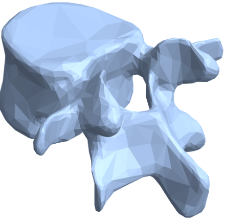
This process involves analyzing how actual patient anatomy compares to an ‘idealized’ model at the site of a planned surgery. In our case, we perform this analysis at the fourth lumbar vertebra (L4) in the lower back. We use Wolfram’s AnatomyPlot3D to serve as our baseline model of an L4, shown here.

2. Create Mesh Regions of Standardized & Actual Anatomy

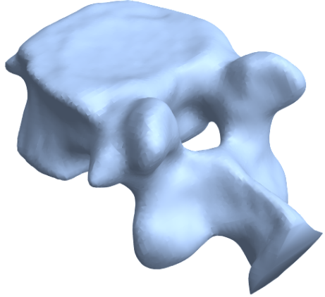
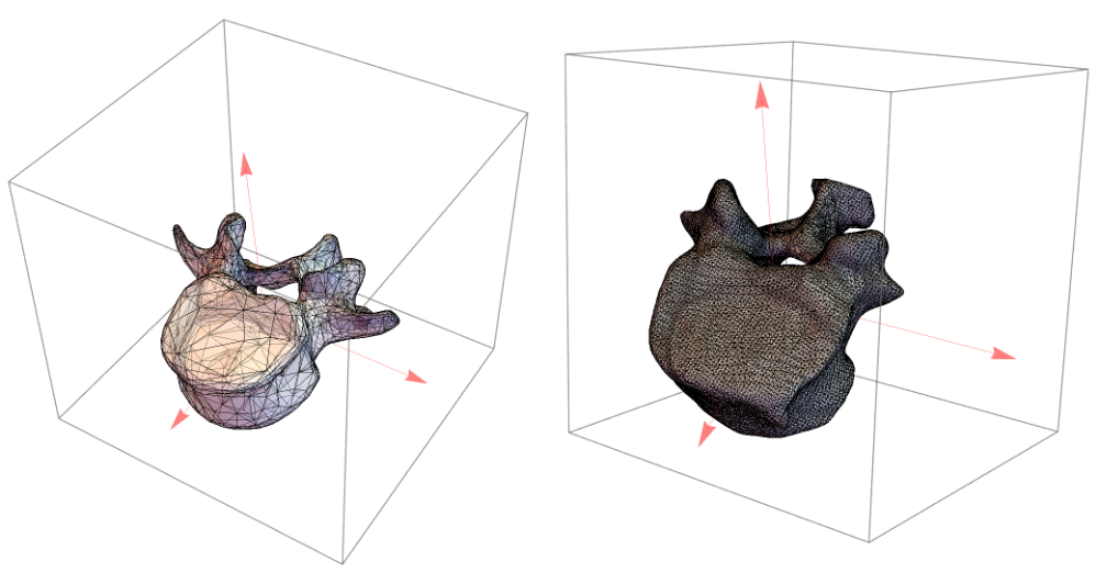
Next, we use the idealized model of the L4 from Wolfram’s AnatomyPlot3D to create a mesh reconstruction representing a baseline L4 shape (below image, left). Then we do the same thing with actual patient data. However, for patient data, we use preoperative medical imaging to construct our 3D model, then create the mesh (below image, right) . This results in two mesh objects representing an actual patient’s anatomy that can be compared against the idealized L4.
​
In[4]:=
graphicsComplex=Cases[anatomyPlot,_GraphicsComplex,Infinity][[1]]​​vertices=graphicsComplex[[1]];​​faces=graphicsComplex[[2]];​​mesh=MeshRegion[vertices,faces];

3. Normalize and Align Models

To ensure tractable and accurate comparison, we center both models at the origin and scale them to have the same bounding box size. This scales them to roughly the same size and position in three dimensional space. Additionally, we compute the moment of inertia for each object and use the resulting inertial axes to align them in three dimensional space, adding a layer of rotational invariance to the workflow.
centerMesh[mesh_]:=Module[{centroid=RegionCentroid[mesh]},TransformedRegion[mesh,TranslationTransform[-centroid]]]​​scaleMesh[mesh_]:=Module[{bounds,scale},bounds=RegionBounds[mesh];scale=1/Max[Abs[bounds[[All,2]]-bounds[[All,1]]]];TransformedRegion[mesh,ScalingTransform[{scale,scale,scale}]]]​​​​idealL4Centered=centerMesh[mesh];​​realL4Centered=centerMesh[realL4];​​idealL4Scaled=scaleMesh[idealL4Centered];​​realL4Scaled=scaleMesh[realL4Centered];​​
At this point, the models for both the idealized version of an L4 and actual patient L4 are at the same position in space, scaled to similar size, and rotationally aligned. This results in two models superimposed upon each other:

4. Select Corresponding Landmarks on Both Models

We now select several bony landmarks on the L4 to represent how much the shape of these models vary, recording the (x,y,z) coordinates of the vertex closest to each landmark. These landmarks should be widely dispersed throughout the mesh, preferably at locations that are easily identifiable. The transverse and spinous processes, for example, were in our list of landmarks since they are fairly well-distributed and easily recognizable locations.
​
Record the x,y,z coordinates for several landmarks of interest, as the distance between these corresponding points on the idealized and actual L4 models will be critical for precision.
​
(*RecordcoordinatesofspecifiedlandmarksonIDEALIZEDL4model*)​​selectedPointsIdeal=​​{{-0.393538,-0.134859,0.245185},(*1.Transverse,R*)​​{0.46602,0.228979,0.0924495},(*2.Transverse,L*)​​{-0.157095,0.492058,0.0794397},(*3.Spinous,Distal*)​​{-0.0525539,0.185103,0.109399},(*4.Spinousforamen,mid*)​​{-0.332745,0.227146,0.070902},(*5.Lamina,R*)​​{0.147556,0.351988,0.0381157},(*6.Lamina,L*)​​{0.100378,-0.416301,-0.160726},(*7.Bodyapex,Proximal*)​​{-0.0292371,-0.243152,-0.362736}}(*8.Bodyapex,Distal*)​​​​(*RecordcoordinatesofsamelandmarksonREALL4model*)​​selectedPointsReal=​​{{-2.80885,-1.04947,21.0999},(*1.Transverse,R*)​​{2.32872,0.620966,19.625},(*2.Transverse,L*)​​{-1.49497,2.93801,20.4766},(*3.Spinous,Distal*)​​{-0.672596,0.548229,20.0854},(*4.Spinousforamen,mid*)​​{-2.52529,1.71904,19.6513},(*5.Lamina,R*)​​{0.855743,2.09096,19.46},(*6.Lamina,L*)​​{0.357114,-3.54186,18.2465},(*7.Bodyapex,Proximal*)​​{-0.363195,-2.23349,16.6463}(*8.Bodyapex,Distal*)​​}

5. Vector Mapping and Radial Basis Function Interpolation

After we have the coordinates for all corresponding landmarks in each model, we can measure the distance between the specified vertex at each location. This returns a list of geometric distances showing how much the patient’s L4 vertebra deviates from the standardized L4 model at each bony landmark:
From these sets of distances, we then create a vector field mapping both distance and directional difference between each corresponding landmark in the two models in Euclidean space. We use the resulting vector field for our radial basis function in the next step, generalizing these differences across the entirety of both meshes. We can now use a radial basis function to interpolate these observed distance variations across the entirety of the patient L4 mesh. This can be thought of as taking an “average variation” from the selected bony landmarks and applying a similar transformations to every other vertex in the patient’s L4 mesh.
Through this process, we create a way for robotic navigation systems to better understand the individual anatomy of patients prior to and during surgical procedures. They become aware of where patient anatomy diverges from normal, learning to anticipate the form and function of unique individuals.

Importance for Surgical Robotics

Accurate alignment of anatomical models is vital in developing coordinate systems for surgical robots. Coordinate systems such as the workflow presented above play a central role in alignment. These coordinate systems enable robots to:
​
​1. Navigate Anatomical Structures: ​
​Robots can move precisely in relation to complex anatomical landmarks, reducing the risk of damaging critical structures.
​
​2. Enhance Surgical Accuracy: ​
​By working within an accurately mapped coordinate system, surgical robots can perform operations with higher precision than human hands alone.
​
​3. Standardize Procedures: ​
​Creating a standardized coordinate system allows for consistency across different procedures and patients, facilitating better training and reproducibility of surgical techniques.
​
​4. Integrate with Imaging Technologies: ​
​Aligning anatomical models with real patient data helps in integrating various imaging modalities (CT, MRI) into the surgical workflow, providing real-time guidance and enhancing decision-making.
​
By leveraging the process described above, we can create a robust and accurate system that maps patient-specific anatomy to a standardized reference model. Such a framework can inform advanced robotic surgical systems, ultimately improving patient outcomes and advancing the field of minimally invasive surgery.

Acknowledgments

I would like to thank Stephen Wolfram, Matteo Salvarezza, Maria Sargsyan for their valuable input and guidance in creating and implementing this project.

References

This is our preferred reference style. You may use “et al.” if there are more than two authors.
1
.
D. Farivar, T.T. Kim, et al. (2023), “Complications Have Not Improved With Newer Generation Robots,” Global Spine Journal. doi:10.1177/21925682231216081.
2
.
M. D’Souza, J. Gendreau, et al. (2019), “Robotic-Assisted Spine Surgery: History, Efficacy, Cost, And Future Trends,” Robotic Surgery: Research and Reviews. doi: 10.2147/RSRR.S190720.

Cite This Notebook

“Creating an Anatomic Coordinate System for Robotic Surgery using Real and Idealized L4 Vertebrae”
by Logan Nye​
​https://community.wolfram.com/groups/-/m/t/3209088