The Enigma machine is one family of ciphering machines of which the Germans used during World War II to encode and decode messages. The Enigma is a “simple” ciphering device employing poly-alphabetic substitution by several means; when a key on the keyboard is pressed an electric current passed into (1) first a plug board; (2) three rotors; (3) a reflector; (4) back through the same three wheels in the opposite direction; (5) and finally back through the plug board, and then lit a lamp under a letter indicating the coded letter. In total, a letter could be interchanged up to nine times. Here is a very brief explanation of the Enigma, its variations, uses, and three Enigma simulators at the end.
The Plugboard
The Plugboard
The "plugboard", or steckerbrett, connected and swapped two letters immediately after pressing a key on the keyboard. The plugboard could have anywhere from 0 to 13 wires. Typically 10 wires were used, resulting in interchanging 20 letters and keeping 6 letters unchanged, or unsteckered. The plugboard connections are shown as pairs of letters that are being switched, i.e.
AQ BE DG HS IW JZ KX LM NR UY
or in table form:
A | B | C | D | E | F | G | H | I | J | K | L | M | N | O | P | Q | R | S | T | U | V | W | X | Y | Z |
Q | E | C | G | B | F | D | S | W | Z | X | M | L | R | O | P | A | N | H | T | Y | V | I | K | U | J |
Notice the interchanged letters are always paired, and non-interchanged letters pass through unchanged.
The Rotors
The Rotors
After the plugboard, the Enigma used three rotors (later changed to four) chosen from a total of five (later eight were supplied). Each rotor was wired to interchange one letter to another for all 26 letters. This can be represented by the table:
A | B | C | D | E | F | G | H | I | J | K | L | M | N | O | P | Q | R | S | T | U | V | W | X | Y | Z |
L | E | Y | J | V | C | N | I | X | W | P | B | Q | M | D | R | T | A | K | Z | G | F | U | H | O | S |
The Turnover
The Turnover
The rotors also moved somewhat like the odometer of a car. Each time a key is pressed, the first, or right most rotor advances one setting before the electric circuit passes through the machine encoding a letter. When the rotor reaches its “turnover” letter, pawls and ratchets advance the middle rotor one notch. When the middle rotor reaches its turnover position the third or left-hand rotor advances one position. Under certain circumstances the middle rotor undergoes a “double-step” advancement, moving with two consecutive key-presses.
The Reflector
The Reflector
After passing through all three rotors, the current passed into a reflector to change the direction of current to pass back through the three rotors in the opposite direction, back through the plugboard, and finally to the lamp. The reflector can be represented in table form as
A | B | C | D | E | F | G | H | I | J | K | L | M | N | O | P | Q | R | S | T | U | V | W | X | Y | Z |
E | J | M | Z | A | L | Y | X | V | B | W | F | C | R | Q | U | O | N | T | S | P | I | K | H | G | D |
The pairing is similar to the plugboard in that each letters is paired with a second letter in both occurrences, except that all 26 letters are paired unlike the plugboard which only paired 20 letters.
The Enigma was supplied with two reflectors of which one was selected. This gives a total number of nine possible interchanges: plug boardrotor 1rotor 2rotor 3reflectorrotor 3rotor 2rotor 1plug board.
The Ring Setting
The Ring Setting
The rotors had one more level of encryption which is called the ring setting. When the Enigma was in use a letter on each rotor was displayed in a window indicating the position of that rotor. A ring on the rotor could be rotated that would offset the letter displayed from the actual position of the wiring, but more importantly, the turnover position is changed. Consider a rotor with only six letters. In standard position the rotor may show A (in red) in the window and swap X-A, with the turnover letter in blue. With a ring setting of 2, an A may still show in the window, but the rotated wiring will swap P-E. More importantly, this also means the turnover position is also offset from its standard position increasing the cryptographic strength.
Manipulate[Module[{new},new=Append[Transpose[RotateRight[Transpose[{rotor[[1]],rotor[[2]]}],n-1]],rotor[[3]]];Grid[Transpose[new],Background{{Lighter[Yellow,.7],Lighter[Yellow,.7],Lighter[Red,.7]}},FrameAll,AlignmentBottom]],Spacer[{0,10}],Row[{Style["n=",14,Italic],Style[Dynamic[n-1],14],Control[{{n,1,""},6,1,1,Slider,Appearance"Vertical",ImageSize{10,100}}]}],Initialization(rotor={{"X","G","L","S","P","D"},{"A","B","C",Style["D",Blue,Bold],"E","F"},{Style["A",Bold,Red],"B","C","D","E","F"}}),ControlPlacementLeft,PaneledFalse,AppearanceElementsNone]

Wiring for the Enigma 1 ~ M1 Version
Wiring for the Enigma 1 ~ M1 Version
Below is the wiring for the MI Version. Note: the reflector UKW-A was only briefly used prior to WWII. UKW-B and UKW-C were the two reflectors supplied with the Enigma.
Wheel | ABCDEFGHIJKLMNOPQRSTUVWXYZ | Turnover |
I | EKMFLGDQVZNTOWYHXUSPAIBRCJ | Q |
II | AJDKSIRUXBLHWTMCQGZNPYFVOE | E |
III | BDFHJLCPRTXVZNYEIWGAKMUSQO | V |
IV | ESOVPZJAYQUIRHXLNFTGKDCMWB | J |
V | VZBRGITYUPSDNHLXAWMJQOFECK | Z |
UKW-A | EJMZALYXVBWFCRQUONTSPIKHGD | |
UKW-B | YRUHQSLDPXNGOKMIEBFZCWVJAT | |
UKW-C | FVPJIAOYEDRZXWGCTKUQSBNMHL |
The wiring of the five rotors was identical for Enigma versions M1, M2, M3, and M4.
Wiring for the Enigma I ~ M3 & M4 Version
Wiring for the Enigma I ~ M3 & M4 Version
The wiring for the M4 with three additional rotors, and the two extra rotors designated beta and gamma:
Wheel | ABCDEFGHIJKLMNOPQRSTUVWXYZ | Turnover |
ETW | ABCDEFGHIJKLMNOPQRSTUVWXYZ | |
I | EKMFLGDQVZNTOWYHXUSPAIBRCJ | Q |
II | AJDKSIRUXBLHWTMCQGZNPYFVOE | M |
III | BDFHJLCPRTXVZNYEIWGAKMUSQO | V |
IV | ESOVPZJAYQUIRHXLNFTGKDCMWB | J |
V | VZBRGITYUPSDNHLXAWMJQOFECK | Z |
VI | JPGVOUMFYQBENHZRDKASXLICTW | ZM |
VII | NZJHGRCXMYSWBOUFAIVLPEKQDT | ZM |
VIII | FKQHTLXOCBJSPDZRAMEWNIUYGV | ZM |
Beta | LEYJVCNIXWPBQMDRTAKZGFUHOS | |
Gamma | FSOKANUERHMBTIYCWLQPZXVGJD | |
UKW-B | ENKQAUYWJICOPBLMDXZVFTHRGS | |
UKW-C | RDOBJNTKVEHMLFCWZAXGYIPSUQ |
Note that the two reflectors have different wiring than the M1 version. Using the combination of the Beta extra rotor and the UKW-B reflector made the M4 completely compatible with the M1.
Diagram Showing the Encoding of Four Key Presses for the Letter “A”
Diagram Showing the Encoding of Four Key Presses for the Letter “A”
Consider an Enigma with three rotors containing only six letters and the given wiring:

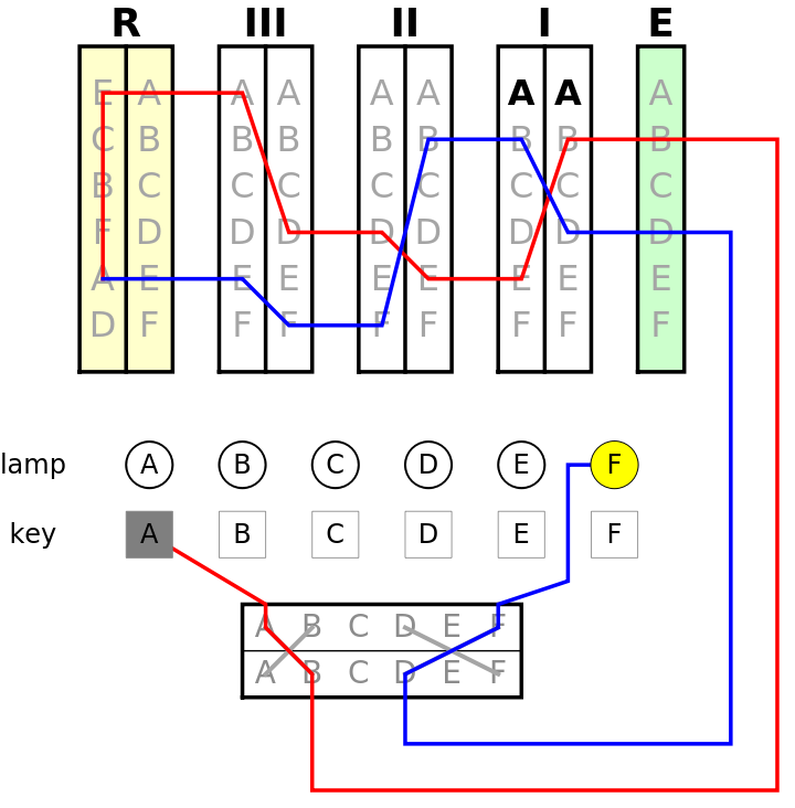
The first encoding of A lights up F: 1) Pressing A passes current to the plugboard and is swapped with B 2) B enters the entry wheel in the B position, and also into rotor 1 at B 3) Rotor 1 wires B to E, and so enters rotor 2 at E 4) Rotor 2 wires E to D, and enters rotor 3 at D 5) Rotor 3 wires D to A, and enters the reflector at A 6) The reflector reflects A to E, so exits at E into rotor 3 7) Going in reverse, rotor 3 has E wired to F, and enters rotor 2 at F 8) Rotor 2 has F wired to B, and enters rotor 1 at B 9) Rotor 1 has B wired to D, and enters the entry wheel at D 10) Back through the plugboard D is swapped to F 11) Finally lighting up the F bulb.The next key-press advances the first rotor a notch, resulting in A encoding to E; a third keypress advances the rotor again encoding A to C; and finally a fourth key-press also encodes A to C but by using a completely different path.
Mathematics of the Enigma
Mathematics of the Enigma
The success of the Enigma was due to the number of initial settings that were possible. Let’s look at the number of possible settings using the typical 3-rotor Enigma using five possible rotors, ring settings for the rotors, two possible reflectors, and a plugboard with 0 to 13 wires.
Plugboard Combinations
Plugboard Combinations
For simplicity, suppose only 4 wires are used swapping a total of eight letters. For each wire we need to choose two letters to swap. Doing this with all four wires leads to
26! 24!2! 24! 22!2! 22! 20!2! 20! 18!2! 26! 18! 4 2 |
or, in general, for n wires we have
The total number of n pairings for 0 to 13 wires is
The total number of plugboard combinations is 532,985,208,200,576. In practice, ten wires were always used which actually decreased the maximum possible cryptographic strength.
The Rotors Combinations
The Rotors Combinations
The next step is to choose the three rotors:
The ring settings of the first two wheels affect the turnover position of the next rotor (the third rotor does not turnover the reflector, so its ring setting does nothing to the cryptographic strength.) Since each of the first two wheels have 26 positions we have
In addition, each of the three rotors have 26 initial settings giving the total number of starting positions:
Reflector Combinations
Reflector Combinations
Finally, the last setting is the reflector of which there were typically two to choose one from. Multiplying all of these settings together gives the total number of possible starting positions of the Enigma:
This is the total number of initial settings assuming there could be 0 to 13 plug-board wires used. However, since the Germans always used 10 wires, the total number of starting positions in practice is
Decoding a Message
Decoding a Message
The Germans used several different techniques to encode and decode a message. Each branch used different methods and had different key sheets and key codes. This caused the same branch to communicate without other branches deciphering their messages. Below is one method for encoding a message.
Monthly key sheets were an integral part in keeping messages as secure as possible. The key sheets listed out the day of the month (Datum), the rotor order (Waltzenlage), the ring setting (Ringstellung), the plugboard wiring (Steckerverbindungen), and a key group (Kenngruppen). Below is a recreation of an actual key sheet:
Monthly key sheets were an integral part in keeping messages as secure as possible. The key sheets listed out the day of the month (Datum), the rotor order (Waltzenlage), the ring setting (Ringstellung), the plugboard wiring (Steckerverbindungen), and a key group (Kenngruppen). Below is a recreation of an actual key sheet:
To verify that a valid key was used for a particular message a five-letter group called Buchstabenkenngruppe would be at the beginning of a message. The Buchstabenkenngruppe is composed of two random letters along with one group of the four Kenngruppen. For example, on October 25, a possible Buchstabenkenngruppe would be DFTBA, or PNCMK, etc. This group of five letters is at the beginning of the message, but is not part of the message. It is included only to verify that a valid key was used to encode the message.
LWUKD OCEZE RJTNP RQVRN QEA
To decode a message, a preamble was sent before the message indicating the time, the number of parts, the number of letters, and most importantly, the key code:
The Mathematica Enigma Simulators
The Mathematica Enigma Simulators
The following manipulates accurately simulate the Enigma I M1 3-rotors (5 total), the Enigma I M3 3-rotor (8 total) used by the German Army after 1942, and the Enigma I M4 4-rotor (8 total) plus two extra rotors, Beta and Gamma. These manipulates can be used to decipher actual WWII Enigma enciphered messages.
The Wehrmacht Enigma I ~ Version M1
The Wehrmacht Enigma I ~ Version M1
The Wehrmacht Enigma I ~ Version M3
The Wehrmacht Enigma I ~ Version M3
The Kriegsmarine Enigma I ~ Version M4
The Kriegsmarine Enigma I ~ Version M4
The Code Book Generator
The Code Book Generator
Module for Creating a code book MakeMonthCode[days,version]:
CITE THIS NOTEBOOK
CITE THIS NOTEBOOK
The German Enigma Enciphering Machine
By Charles Stevens
Wolfram Community, STAFF PICKS, February 6, 2024
https://community.wolfram.com/groups/-/m/t/3117219
By Charles Stevens
Wolfram Community, STAFF PICKS, February 6, 2024
https://community.wolfram.com/groups/-/m/t/3117219