WOLFRAM NOTEBOOK

Trees are vital to our lives. Whether it be through the filtration of air and water, quality lumber, or just their natural beauty, trees have served as a multipurpose organism since the dawn of humanity. Among their uses, trees provide shade; shade allows solar respite for animals, humans, and perhaps most currently relevant, our ever urbanizing and heat-prone landscape. In this project, I model 2D and 3D shadows of generated trees using vector projections.

Introduction

Sunlight penetrates a tree’s crown. The tree creates a shadow. Everyone who has touched grass knows this fact. But how exactly do these shadows look? In my project, I investigate this question. I first begin in 2D, creating trees and projecting their shadows with vectors. I then move onto 3D, using a slightly different strategy.

The Method of 2D Vectors

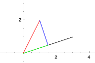
Vectors are quantities with magnitude and direction, but for our purposes, vectors can be thought of as a point or a line. Vector projections can be seen as the “shadow” (green) of Vector A (red) on Vector B (black}, at an angle perpendicular to Vector B. I use this idea to create our shadows. I start with a vertical sunlight vector, so that the vector projection will just be the shadow. I then examine angle shadows, extending Vector D to create a full shadow at any angle.
Vector A: Red; Vector B: Black; Vector C: Green, Vector D: Blue. Vector C overlaps Vector B.

The Method of 3D Vectors

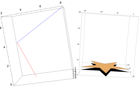
For 3D trees, I use a slightly different strategy. Instead of finding the shadow perpendicular to the sunlight angle, I project straight onto the xy plane (the shadow) by finding the xy intersection point of a vector point and a sunlight vector angle. Finally, I import an image, turn it into a polygon, and place it where necessary to create and project leaves.
On the left, the blue 3D vector is being projected to the xy axis (red vector) at a specified sunlight angle. This is the basis for our 3D angle projections. On the right, I project each of the points of a star onto the ground, and then connect them back again on the xy plane to form a shadow.

2D Trees

First, I create trees in 2D. Then, I start at an angle with the sun straight above, then I code functions to accommodate different angles.

Tree creation and setup for 2D projections

First, I have to create functions to display vectors and create trees to project.

Defining 2D Vector Functions

I define functions to graph any 2D vector. If specified, the vectors can start at any point, but if not, the vectors will start at the origin. This will serve as the foundation for all of our projections.
In[]:=
vec[vector_List,start_List]:=Graphics[{Green,Line[{{0,0}+start,vector+start}]},Axes->True,PlotRange->All]vec[vector_List]:=vec[vector,{0,0}]

Modifying the Tree Bender Demonstration

To start, we must generate trees to model. Wolfram does not have any really useful built in tree models, so I modified Wolfram’s tree bender demonstration. Importantly, because this demonstration randomly generates trees, it sacrifices known tree patterns and a bit of realism.
These points define the initial line (the trunk) of the tree.
yInitialOffset=0.9;xInitialOffset=0.25;
These define the initial x and y (mirrored) endpoints of the branches.
firstBranchEndpoint={{yInitialOffset,-xInitialOffset},{xInitialOffset,yInitialOffset}};secondBranchEndpoint={{yInitialOffset,xInitialOffset},{-xInitialOffset,yInitialOffset}};
Wolfram’s tree bender demonstration creates a list of two lists, or essentially two points, for every previous vector. This can be thought of branching property of a tree.
The demo takes a start and end point to a line, adds the end point with the dot product (how similar two vectors are) of the vector of the line and the endpoint of the first branch point, and then adds a random value to generate our tree. This is all to add "predictable variation" in these trees.
In[]:=
rand:=RandomReal[{-0.3,0.3}];creationFunc=Function[{point},{{point[[2]],point[[2]]+firstBranchEndpoint.(point[[2]]-point[[1]])+rand},{point[[2]],point[[2]]+secondBranchEndpoint.(point[[2]]-point[[1]])}}];
The function nestFunc applies creationFunc over and over to create a list of start and end points. In terms of actual trees, this is important because we need to create two branches from each branch over and over. The Function startendlist uses this nestFunc and specifies the starting point and the number of generations.
In[]:=
nestFunc=Function[Flatten[Map[creationFunc[#]&,#],1]];startendlist=NestList[nestFunc[#]&,{{{0,0},{0,1}}},3];
Graphing our points :
In[]:=
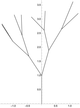
Graphics[Line/@Flatten[startendlist,1],Axes->True]
Out[]=
Now, I modify the tree bender vectors in the form {start, end} to our own vector function, which is in the form {vector, start}. We take each vector in the form {start, end} to become {end-start, start}. We can take this step because if a vector goes from Point A to Point B, it can be displayed as the vector of the distance between them (Vector B-A) starting at Point A. I chose to take this step as it is easier to project multiple vectors (as we I will be doing with trees) in the latter form.
In[]:=
truevectors=Flatten[(#[[All,2]]-#[[All,1]])&/@startendlist,1];startpoints=Flatten[#[[All,1]]&/@startendlist,1];finalform=Thread[{truevectors,startpoints}];
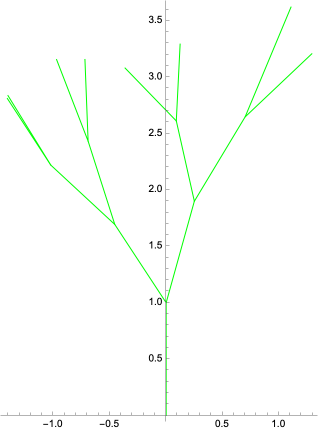
We see our modified points with our own vector function.
In[]:=
treeshow=Show[Table[vec[x[[1]],x[[2]]],{x,finalform}]]
Out[]=
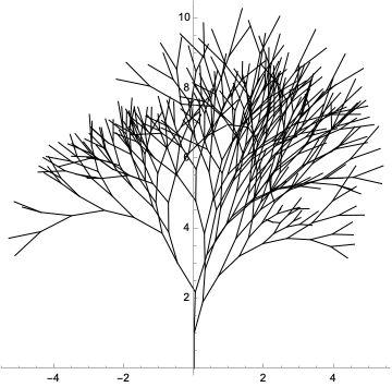
We achieve simple trees like this, but I can easily add complexity by changing the number of generations. However, doing heavy projection work with these trees is computationally heavy and thus will not be used primarily in this project.
In[]:=
startendlist2=NestList[nestFunc[#]&,{{{0,0},{0,1}}},8];
In[]:=
Graphics[Line/@Flatten[startendlist2,1],Axes->True]
Out[]=

2D projections

Now that we have our tree, I define a function to project different vectors, and then use this function on all the vectors of our tree.

Top-down 2D Tree Shadows

First, I define a top projection (image the sunlight right above the tree) that takes a given vector, where to project that vector, and where to start that vector.
Let’s look at the simplest case. Starting at {1,1}, the vector {1,5} is projected onto {2,0}. We see the vector, the projection, the connections between them, the projection mapped onto the ground, and a opaque rectangle to loosely model a shadow.
This top function is designed to take a vector to project onto, but cannot really be used for angle projections, as the angled vectors do not extend to the ground. Thus, I set the vector to project on to have an x value of 0, so the tree is projected onto the x axis, creating some shadow. I run this function through our generated tree, and we can see our opaque rectangles stacking to loosely model different amount of shadow.

Angle 2D Tree Shadows

To model tree shadows at an angle, I modify our top-down 2D projection.
Let’s look at a basic example. Starting at the point {2,3}, we can see the vector {1,2} projected onto the vector {3,4}. The vector {3,4} is perpendicular to the sunlight angle, but for our purposes, setting an exact sunlight angle isn’t too important (will will play around with sunlight angle in a later manipulate). Importantly, the projection is extended to the x-axis, which I do in code by finding the slope of the vector defining the distance between the original vector and its projection. Finally, I form an opaque polygon between the important points to generate the earlier shadow stacking effect.
Applying our function to our tree, we obtain this visualization.
The guiding vectors are a bit messy. By removing some vectors, we can get a better view of the shadow.
On the top, we can see different clean, shadow angles, and on the bottom, we can see the polygon shadow rendering of an 8 generation tree.

3D Trees

Next, I create 3D trees and project them in different forms.

Tree Creation and Setup for 3D Projections

First, I set the foundation for projecting 3D trees: creating the trees themselves, and creating 3D vector functions.

Defining 3D Vector Functions

I define a similar function as our 2D for 3D vectors. Importantly, I add the option for a color specification, as it allows better viewing of trees, which is needed in the more complex 3D world.
An example of the vector {5,4,3} starting at {4,2,3}, colored in Blue.

Modifying the Tree Bender Demonstration for 3D

I take our tree bender sample code again, but I modify it for 3D. Many steps resemble the 2D modification to the tree bender, so I will not be explaining as in depth here.
I add a z initial offset, as well as a third coordinate.
Again, I define random values to add to previous points, so that we can randomly generate a tree. I have assumed that the z value only increases, and while this trend isn’t universal (think of a weeping willow tree), the resulting tree generation is generally more realistic.
I undergo a similar process to our 2D tree creation.
We set the generations to be 8, and while increasing generations could result in a more realistic tree, it takes significantly more computational power, especially in 3D.
It is the last argument of the function myPoints3D that specifies the number of generations.
Again, because our points are still in {start, end} form, I modify it to accommodate our vector function, which is in {vector, start} form.
Showing the 3D tree in our own vector function;

3D Projections

In this section, I project our 3D projections at an angle and top-down.

Top-down 3D Tree Shadows

Top-down 3D vector trees are easy enough; I just set z=0 for most of our equations.
We draw out our vector, guiding lines, and the polygon, and we apply it to all the tree branch vectors.
Unfortunately, the shadow stacking method I used in 2D is very messy in 3D, so it’s not as effective. However, I can mess around with the vectors and visual settings to yield the following cool graphic:
The visualization is neat, but I still want to see the shadow of the tree, so I simplify the function by removing some guiding lines. This better shows our shadow.

Angle 3D Tree Shadows

Angle projections in 3D are much harder than 2D. Instead of extending vector projections, I set a “sunlight vector” representing the sunlight angle and use this to solve for an intersection point bewteen the xy plane and our branch vectors.
This function solves the xy intersection point for any given vector and a sunlight vector,
Making an anglexyprojection function, I draw guiding vectors and a opaque polygon from the points, similar to our top projection in 3D. I apply this to all the vectors of the tree.
The visual on the left is what the code generates. Similar to our top-down shadow, messing around with visual settings yields the visual on the right.
Again, I still want to see the shadow, so I get rid of the extra guiding lines in a simpler function.
Projecting onto an arbitrary vector, we obtain something like this.
We can also see different projections angles by changing the values of the vector to project onto. In this image collage, we see a the project-onto-vector with a relative higher x value, y value and z value.

Incorporating Leaves

One cannot have a tree without leaves. In this section, I append leaves to the end of each branch and create their shadow.

Adding Leaves to the 3D Tree

I begin by taking a picture and meshing it. Our tree branches are random, so they aren’t really specific to any type of tree. I randomly choose a white oak leaf.
More importantly, I find the coordinates of the leaf and modify them for our tree by scaling down and translating all the coordinates so that the leaf is much smaller and starts at {0,0,0}.
I create a simple function to turn our leaves into 3D.
Next, I set a function that can put a leaf at any given coordinate point.
Next, I find the endpoints of the branches of our tree to know where to put our leaves. Because our list of points is already sectioned into sublists for each generation, we can just take the last sublist to obtain the last generation of branches. I specifically chose to use the original points of the tree creation ({start, end} form, not our modified {vector,start} form), so I just take the second index (end) to obtain where the coordinates of the last generation of branches are.
Next, I rotate these leaves randomly, so our tree can look more natural. I simultaneously place these leaves at the branch endpoints.
Finally, we tack on our leaves on our previous tree to show a completed tree.

Top-down 3D Leaf Tree Shadow

First, I map our leaves onto the ground, or z=0, by finding the intersection point of each point on the leaf to the the ground, and then making a polygon of that. I use a straight sunlight vector to do this.
Next, I combine our leaf shadows with our earlier created tree and its top down shadow for a full picture. Quite nice!

Angle 3D Leaf Tree Shadow

I project our leaves at an angle. It’s pretty much the same essence as our earlier top-down projection, but I just line project onto a different, angled sunlight vector.
Again, we can modify the sunlight vector to show different angles. This is our final product.
To conclude this project, we have a little fun by adding a sky and a ground.

Conclusion

Applications and Future Improvements

In conclusion, I have coded functions that successfully model shadows of trees. Given any random tree and any leaf generation, my functions will create an accurate shadow projection. Importantly, there are greater implications: these functions are not limited to just trees. My strategy can be adapted to any set of vectors (branches), or even polygons (leaves). Furthermore, my shadow vector technique is easily modifiable: future users can and should do a number of things: modify lighting to obtain neater visuals, remove and add different vectors, append additional polygonal features...

Nevertheless, there is still work to be done. Modifying the tree bender creates random trees, but because of this, my trees are not entirely realistic, nor able to be mapped to different tree species. In the future, I hope to create algorithms that will create species-specific trees, so I can analyze the implications of different shadow patterns. Additionally, my leaves are only placed at the tips of the most outer generation of branches, while in real life, leaves are found scattered throughout the branches, which themselves are also spread throughout the tree.

Acknowledgements

I would like to thank my mentor, Anika Patel, for her invaluable feedback, instruction, and guidance throughout my project.
I would also like to thank all the students, TAs, mentors, directors, and CEOs who have made my experience at this program a phenomenal one.

References

Gray, T. (2011, March). Tree Bender - Wolfram Demonstrations Project. Demonstrations.wolfram.com. https://demonstrations.wolfram.com/TreeBender/

CITE THIS NOTEBOOK

Wolfram Cloud

You are using a browser not supported by the Wolfram Cloud

Supported browsers include recent versions of Chrome, Edge, Firefox and Safari.


I understand and wish to continue anyway »
You are using a browser not supported by the Wolfram Cloud. Supported browsers include recent versions of Chrome, Edge, Firefox and Safari.