CITE THIS ARTICLE: Rhombic enneacontahedron explained by Sándor Kabai, Wolfram Community, SEP 28 2022
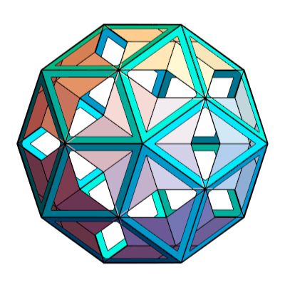
Rhombic enneacontahedron (RE) is constructed based on its relationship to rhombic triacontahedron (RT). There are 60 thick faces with square root 2 diagonal ratio, and 30 faces with diagonal ratio golden ratio squared. The thin rhombuses correspond to those of medial rhombic triacontahedron (MRT). An RE is constructed from various solids in a space filling fashion.
Thick rhombus
Thick rhombus
In[]:=
rt=PolyhedronData["RhombicTriacontahedron","Faces"];sp=Sphere[{0,0,0},0.03];fi=GoldenRatio;alf=ArcTan[fi];bet=ArcTan[1/fi];bet1=ArcTan[1/fi^2];gam=ArcTan[Sqrt[2]];(*halfdiagonalsofthickrhombus*)xt=Cos[gam];yt=Sin[gam];(*halfdiagonalsofthinrhombus*)x1=Cos[bet1];y1=Sin[bet1];(*thickrhombus*)vA={xt,0,0};vB={0,yt,0};vC={-xt,0,0};vD={0,-yt,0};(*central*)thick1=Polygon[{vA,vB,vC,vD}];(*tiptakentoorigin*)thick2=Translate[thick1,{0,-yt,0}];(*Forcalculationoftiltangleconsiderthetopviewofthickrhombus*)t=xt/Tan[2Pi/10];tilt=ArcCos[t/yt];thick3=Table[Rotate[Rotate[thick2,tilt,{1,0,0}],i2Pi/5-Pi/2,{0,0,1}],{i,5}];(*sd=halfshortdiagonalofRT*)sd=Cos[alf];(*Thehalflongdiagonalofthinrhombusisx1,sotheincreaseoffittiingRThastobex1/sd*)inc=N[x1/sd];(*sizeoftiporRTisfi*)N1+
1
2
5
;(*elevatetothetipoflargeRT*)el=N[x1fi/Tan[bet]];thick4=Translate[thick3,{0,0,el}];thick5=Rotate[Rotate[thick4,Pi,{0,0,1}],2bet,{0,1,0}];thick25=Table[Rotate[thick5,i2Pi/5,{0,0,1}],{i,5}];thick30=Rotate[{thick4,thick25},Pi,{0,1,0}];rtn=Rotate[Scale[rt,0.999inc],Pi,{0,0,1}];re={thick4,thick25,thick30};Graphics3D[{re},BoxedFalse,SphericalRegionTrue,ViewPoint{0,0,100},ImageSize200]Out[]=

Relationship with RT
Relationship with RT
In[]:=
vArt={1/fi,0,0};vBrt={0,1,0};vCrt={-1/fi,0,0};vDrt={0,-1,0};s1rt={vArt,vBrt,vCrt,vDrt,vArt};s2rt=0.8{vArt,vBrt,vCrt,vDrt,vArt};r1rt=Polygon[Join[s1rt->s2rt]];r2rt=Translate[{r1rt},{0,0,fi}];r3rt=Translate[{r1rt},{0,0,-fi}];r4rt=Rotate[Rotate[{r2rt,r3rt},Pi/2+0.001,{1,0,0}],Pi/2+0.001,{0,1,0}];r5rt=Rotate[Rotate[{r2rt,r3rt},Pi/2+0.001,{0,1,0}],Pi/2+0.001,{1,0,0}];rtp={RGBColor[0,1,1],Scale[Table[Rotate[Rotate[{r2rt,r3rt,r4rt,r5rt},bet,{1,0,0}],i2Pi/5+Pi/2,{0,0,1}],{i,5}],1.5]};Graphics3D[{rtp,thick4,thick25},BoxedFalse,SphericalRegionTrue,ViewPoint{0,0,100},ImageSize300]
Out[]=
Thin rhombus
Thin rhombus
In[]:=
x1=Cos[bet1];y1=Sin[bet1];vA1i={y1,0,0};vB1i={0,x1,0};vC1i={-y1,0,0};vD1i={0,-x1,0};thin1=Polygon[{vA1i,vB1i,vC1i,vD1i}];(*misthedistanceofflatsurfaceofRTiscalvculatedfromldhalflongdiagonalofRT*)ld=Sin[alf];m=N[Sqrt[(fi)^2-ld^2]];(*elevatethin1toaheighm*inc*)thin2=Rotate[Translate[thin1,{0,0,minc}],0,{0,1,0}];(*nowconstarct30thin*)thin3=Rotate[thin2,Pi,{1,0,0}];thin4=Rotate[Rotate[{thin2,thin3},Pi/2,{0,0,1}],Pi/2,{0,1,0}];thin5=Rotate[Rotate[{thin2,thin3},Pi/2,{0,1,0}],Pi/2,{0,0,1}];thin30=Table[Rotate[Rotate[{thin2,thin3,thin4,thin5},bet,{0,1,0}],i2Pi/5,{0,0,1}],{i,5}];Graphics3D[{thin30},BoxedFalse,SphericalRegionTrue,ViewPoint{0,0,100},ImageSize210]
Out[]=

In[]:=
Graphics3D[{re,Green,thin30},ImageSize300]
Out[]=

Relationship with medial rhombic triacontahedron (MRT). The thin rhombuses correspond to those of MRT.
Relationship with cubes.
Note the centroid
Cladding 1
Cladding 2
Cladding 3
In a frame of RE it is possible see how the components are included.
Here are the participants (dodecahedron is not part of the structure, it is here only to indicate how PZ is derived).