Second-Order Digital Filter Design
Second-Order Digital Filter Design


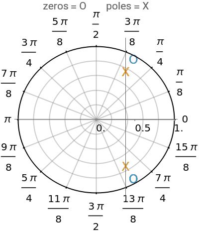

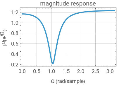
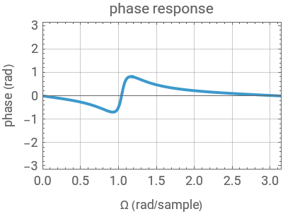
This Demonstration considers the design of a second-order digital filter. Multiple perspectives of the system are shown, including the placement of poles and zeros, a 3D plot of the transfer function in the domain with a highlighted unit circle and the filter magnitude and phase responses. The relationships between the locations of poles or zeros, the frequency response and the 3D plot of are also shown. The transfer function is presented in its general form, along with the corresponding difference equation for the given placement of the poles and zeros. You can change their positions to see how they affect the lowpass, highpass and bandpass digital filters.
z
H(z)
Details
Details
Linear time-invariant (LTI) discrete-time systems are commonly described from different perspectives, including a difference equation and a transfer function , where is a complex variable. The frequency response of the system can be obtained by evaluating on the unit circle. To visualize this, a 3D plot of is shown, with the unit circle highlighted. You can see how the locations of the poles and zeros affect the behavior of the system.
H(z)
z
H(z)
H(z)
The transfer function is given by
H(z)=-2azcosθ+-bzcosθ+
2
z
2
a
2
z
2
b
The difference equation is given by
y(n)x(n-2)-2acosθx(n-1)+y(n-2)-2by(n-1)cosϕ+x(n)
2
a
2
b
This Demonstration focuses on a specific scenario in which the poles are within the unit circle. This configuration ensures a bounded-input, bounded-output (BIBO) stable system. Showcasing different descriptions and representations leads to a better understanding of the performance and design of a first-order discrete-time system. You can vary the locations of the poles and zeros to show how a second-order system can be used as a lowpass, bandpass or highpass filter.
References
References
[1] F. T. Ulaby and A. E. Yagel, Signals and Systems: Theory and Applications, Michigan Publishing, 2018. (Jul 21, 2023) ss2.eecs.umich.edu.
External Links
External Links
Permanent Citation
Permanent Citation
Victor S. Frost
"Second-Order Digital Filter Design"
http://demonstrations.wolfram.com/SecondOrderDigitalFilterDesign/
Wolfram Demonstrations Project
Published: August 7, 2023