ABSTRACT (original article): Many chemical engineering programs teach gas permeation because of its important applications in the oil and gas industry. In fact, it is considered a good replacement for classical separation techniques such as cryogenic technologies, PSA, physical and chemical absorption etc. Gas permeation module modeling can play an important role in both simulation and design of permeation units. In fact, the simulation allows the prediction of the separation performance of gas permeation modules as well as the selection of optimal operating parameters, stage cut and pressure ratio . On the other hand, the design provides useful data such as the module area. Here, we present the theoretical background of this unit operation, and the modeling of a single-stage gas permeation module used to separate multicomponent gas mixtures for the following flow patterns: (1) perfect mixing, (2) one-side mixing, (3) cross flow, (4) co-current flow, (4) counter-current flow. Our numerical simulation methodology is based on Chebyshev orthogonal collocation and arc-length continuation techniques. We apply the proposed methodology to two industrially important systems, which are described in reference (Shindo et al. in Sep Sci Technol 20:445–459, 1985. https:// doi. org/ 10. 1080/ 01496 39850 80606 92): (1) separation of NH3, H2, and N2 gaseous mixture by means of a polyethylene membrane. Such a gas mixture arises in the Haber process. (2) Separation of H2, CH4, CO, N2, and CO2 mixture through a microporous glass membrane. This mixture is important in the partial oxidation of fuels with air and in the steam gasification of biomass. Whenever possible, our results are benchmarked against data obtained from the open literature or predicted using the software Aspen-Plus®. Furthermore, we performed sensitivity analyses where we vary either the stage cut or the pressure ratio in order to investigate the effect of these parameters on both the permeate and retentate compositions as well as on the surface area of the permeation module. Finally, we provide useful tips and computer coding to readers who wish to investigate similar gas permeation problems using our new methodology. CITATION (original article): H. Binous, U. Zahid and A. Bellagi, Modeling for Multi-component Gas Permeation with Orthogonal Collocation and Arc-Length Continuation, Chemistry Africa (2024). DOI: https://doi.org/10.1007/s42250-024-01167-y
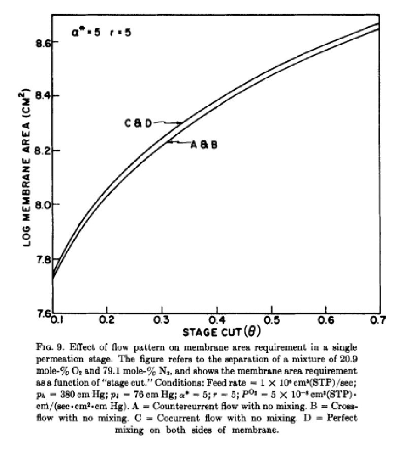
We reproduce Fig. 9 of Ref. 1 using two methods and for the co-current flow pattern case:
(1) the first approach is based on orthogonal collocation and arc-length continuation (for the details of this methodology see Ref. 2),
(2) the second method is based on the work of Wankat and Coker and coworkers (see Ref. 3-6).
Fig. 9 refers to the separation of air components (a mixture of 20.9 mole-% and 79.1 mole-% ). This figure depicts the membrane area requirement as a function of stage cut. In the early seventies, Stern and coworkers did extensive studies of oxygen enrichment as well as the separation of air components (e.g. Ref. 2);
Results for the other flow patterns (i.e., cross flow and counter-current flow patterns) are readily obtained using a similar approach (see Ref. 2).
(1) the first approach is based on orthogonal collocation and arc-length continuation (for the details of this methodology see Ref. 2),
(2) the second method is based on the work of Wankat and Coker and coworkers (see Ref. 3-6).
Fig. 9 refers to the separation of air components (a mixture of 20.9 mole-%
O
2
N
2
Results for the other flow patterns (i.e., cross flow and counter-current flow patterns) are readily obtained using a similar approach (see Ref. 2).
Conditions:
Feed rate = 1 x 1 c (STP)/sec;
Pressures: = 380 cm Hg (high pressure or retentate-side pressure) and = 76 cm Hg (low pressure or permeate-side pressure);
a = 5 (separation factor or ratio of permeabilities);
r = 5; (r is the pressure ratio or/);
= 5 X 1 c(STP) x cm/(sec-c cm Hg) (permeability of oxygen);
t= 2.54x1 cm (thickness of the membrane).
Feed rate = 1 x 1
6
0
3
m
Pressures:
p
h
p
l
a = 5 (separation factor or ratio of permeabilities);
r = 5; (r is the pressure ratio or
p
h
p
l
O
2
P
-8
0
3
m
2
m
t= 2.54x1
-3
0
Solution based on the work of Binous et al. (see Ref. 2)
Separation factor or ratio of permeabilities
α=5;
In[]:=
sol=Solve[y/(1-y)(α((xf-/y)/(1-xf-/(1-y)))),y];
p
l
p
h
p
l
p
h
Permeate mole fraction at the feed side
yi=y/.sol[[1]];
T
hetaisthestagecutandistheretentateflowrate
q
O
q
O
Membrane thickness
t=2.5410^-3;
Permeability of B or N2
P'
B
Derivative matrix
In[]:=
Np=20;d[0,0]=(2Np^2+1)/6//N;d[Np,Np]=-(2Np^2+1)/6//N;yc[i_]:=Cos[iPi/Np]//N;d[i_,i_]:=-yc[i]/(2(1-yc[i]^2))//N;d[j_,k_]:=If[j≠k&&k≠0&&k≠Np&&j≠0&&j≠Np,(-1)^(j+k)/(yc[j]-yc[k])]//N;d[Np,0]=-1/2(-1)^Np;d[0,Np]=1/2(-1)^Np;d[j_,0]:=If[j≠Np&&j≠0,-1/2(-1)^j/(1-yc[j])];d[j_,Np]:=If[j≠Np&&j≠0,1/2(-1)^(j+Np)/(1+yc[j])];d[0,j_]:=If[j≠Np&&j≠0,2(-1)^j/(1-yc[j])];d[Np,j_]:=If[j≠Np&&j≠0,-2(-1)^(j+Np)/(1+yc[j])];Add=Table[d[i,j]//N,{i,0,Np},{j,0,Np}];
Discretization of derivatives of the permeate and retentate mole fractions - Af is total area of the separation module
In[]:=
xp[i_]:=2/AfAdd[[i,j]]x[j];yp[i_]:=2/AfAdd[[i,j]]y[j];
Np+1
∑
j=1
Np+1
∑
j=1
Data
In[]:=
data={t->2.5410^-3,->380,->76,->5/510^-8,(1-theta)10^6,xoa,1010^5};
p
h
p
l
P'
B
q
O
q
f
Equations and boundary conditions - cocurrent flow pattern is assumed
In[]:=
eq3=y[0]yi;
In[]:=
eq1[i_]:=xp[i]==()/(t)(x[i]-y[i])/(y[i]-xf)((1-x[i])α(/x[i]-y[i])-x[i](/(1-x[i])-(1-y[i])))/.data;eq2[i_]:=yp[i]==()/(t)(x[i]-y[i])/(x[i]-xf)((1-y[i])α(/x[i]-y[i])-y[i](/(1-x[i])-(1-y[i])))/.data;
p
l
P'
B
q
f
p
h
p
l
p
h
p
l
p
l
P'
B
q
f
p
h
p
l
p
h
p
l
In[]:=
bc1=xp[1]()/(t)α(xf/-yi)(xf-yi)/yi/.data;bc2=yp[1](xf-yi)/(α-yi(α-1))/((t)/()-((xf-yi)/(()/(t)α(xf/-yi)(xf-yi)/yi))((α-1)(2yi-/xf-1)-/))/.data;
p
l
P'
B
q
f
p
h
p
l
p
h
p
l
q
f
p
l
P'
B
p
l
P'
B
q
f
p
h
p
l
p
h
p
l
p
h
p
l
In[]:=
y[1]=yi/.data;
In[]:=
bc3=x[Np+1]xo/.xoa;
In[]:=
x[1]=0.209;
In[]:=
bc4=thetay[Np+1]+(1-theta)xo0.209/.xoa;
Feed mole fraction of O2
xf=0.209;
In[]:=
sys=Join[Flatten[Table[{eq1[i],eq2[i]},{i,2,Np}],1],{bc1,bc2,bc3,bc4}];
In[]:=
unknowns=Join[Flatten[Table[{{x[i],0.1,0.2},{y[i],0.5,0.4}},{i,2,Np+1}],1],{{a,0.1,0.13},{Af,-5.510^7,-5.010^7}}];
Solution for a particular value of theta - theta = stage cut = 0.1
In[]:=
sol=FindRoot[sys/.theta0.1,unknowns,MaxIterations1000]
Out[]=
{x[2]0.20884,y[2]0.460746,x[3]0.208364,y[3]0.460271,x[4]0.207584,y[4]0.459491,x[5]0.206523,y[5]0.458427,x[6]0.205208,y[6]0.457104,x[7]0.203674,y[7]0.455554,x[8]0.201961,y[8]0.453815,x[9]0.200114,y[9]0.45193,x[10]0.198181,y[10]0.449945,x[11]0.196211,y[11]0.44791,x[12]0.194252,y[12]0.445874,x[13]0.192353,y[13]0.443888,x[14]0.19056,y[14]0.442001,x[15]0.188914,y[15]0.44026,x[16]0.187453,y[16]0.438707,x[17]0.186212,y[17]0.437381,x[18]0.185217,y[18]0.436314,x[19]0.184491,y[19]0.435533,x[20]0.184049,y[20]0.435056,x[21]0.1839,y[21]0.434896,a0.1839,Af-5.44833×}
7
10
Solution based on arc-length continuation
Initial conditions
In[]:=
init1=Flatten@Join[Table[{x[i][0](x[i]/.sol),y[i][0](y[i]/.sol)},{i,2,Np+1}],{a[0](a/.sol),Af[0](Af/.sol),theta[0]0.1}]
Out[]=
{x[2][0]0.20884,y[2][0]0.460746,x[3][0]0.208364,y[3][0]0.460271,x[4][0]0.207584,y[4][0]0.459491,x[5][0]0.206523,y[5][0]0.458427,x[6][0]0.205208,y[6][0]0.457104,x[7][0]0.203674,y[7][0]0.455554,x[8][0]0.201961,y[8][0]0.453815,x[9][0]0.200114,y[9][0]0.45193,x[10][0]0.198181,y[10][0]0.449945,x[11][0]0.196211,y[11][0]0.44791,x[12][0]0.194252,y[12][0]0.445874,x[13][0]0.192353,y[13][0]0.443888,x[14][0]0.19056,y[14][0]0.442001,x[15][0]0.188914,y[15][0]0.44026,x[16][0]0.187453,y[16][0]0.438707,x[17][0]0.186212,y[17][0]0.437381,x[18][0]0.185217,y[18][0]0.436314,x[19][0]0.184491,y[19][0]0.435533,x[20][0]0.184049,y[20][0]0.435056,x[21][0]0.1839,y[21][0]0.434896,a[0]0.1839,Af[0]-5.44833×,theta[0]0.1}
7
10
All unknown variables are functions of s or the arc-length
In[]:=
param={x[2]x[2][s],y[2]y[2][s],x[3]x[3][s],y[3]y[3][s],x[4]x[4][s],y[4]y[4][s],x[5]x[5][s],y[5]y[5][s],x[6]x[6][s],y[6]y[6][s],x[7]x[7][s],y[7]y[7][s],x[8]x[8][s],y[8]y[8][s],x[9]x[9][s],y[9]y[9][s],x[10]x[10][s],y[10]y[10][s],x[11]x[11][s],y[11]y[11][s],x[12]x[12][s],y[12]y[12][s],x[13]x[13][s],y[13]y[13][s],x[14]x[14][s],y[14]y[14][s],x[15]x[15][s],y[15]y[15][s],x[16]x[16][s],y[16]y[16][s],x[17]x[17][s],y[17]y[17][s],x[18]x[18][s],y[18]y[18][s],x[19]x[19][s],y[19]y[19][s],x[20]x[20][s],y[20]y[20][s],x[21]x[21][s],y[21]y[21][s],aa[s],AfAf[s],thetatheta[s]}
Out[]=
{x[2]x[2][s],y[2]y[2][s],x[3]x[3][s],y[3]y[3][s],x[4]x[4][s],y[4]y[4][s],x[5]x[5][s],y[5]y[5][s],x[6]x[6][s],y[6]y[6][s],x[7]x[7][s],y[7]y[7][s],x[8]x[8][s],y[8]y[8][s],x[9]x[9][s],y[9]y[9][s],x[10]x[10][s],y[10]y[10][s],x[11]x[11][s],y[11]y[11][s],x[12]x[12][s],y[12]y[12][s],x[13]x[13][s],y[13]y[13][s],x[14]x[14][s],y[14]y[14][s],x[15]x[15][s],y[15]y[15][s],x[16]x[16][s],y[16]y[16][s],x[17]x[17][s],y[17]y[17][s],x[18]x[18][s],y[18]y[18][s],x[19]x[19][s],y[19]y[19][s],x[20]x[20][s],y[20]y[20][s],x[21]x[21][s],y[21]y[21][s],aa[s],AfAf[s],thetatheta[s]}
In[]:=
sysn=sys/.param;
Auxiliary equation
In[]:=
aux=Sum[x[i]'[s]^2+y[i]'[s]^2,{i,2,Np+1}]+a'[s]^2+Af'[s]^2+theta'[s]^21
Out[]=
2
′
a
2
′
Af
2
′
theta
2
′
x[2]
2
′
x[3]
2
′
x[4]
2
′
x[5]
2
′
x[6]
2
′
x[7]
2
′
x[8]
2
′
x[9]
2
′
x[10]
2
′
x[11]
2
′
x[12]
2
′
x[13]
2
′
x[14]
2
′
x[15]
2
′
x[16]
2
′
x[17]
2
′
x[18]
2
′
x[19]
2
′
x[20]
2
′
x[21]
2
′
y[2]
2
′
y[3]
2
′
y[4]
2
′
y[5]
2
′
y[6]
2
′
y[7]
2
′
y[8]
2
′
y[9]
2
′
y[10]
2
′
y[11]
2
′
y[12]
2
′
y[13]
2
′
y[14]
2
′
y[15]
2
′
y[16]
2
′
y[17]
2
′
y[18]
2
′
y[19]
2
′
y[20]
2
′
y[21]
Unknowns
Initial conditions on the derivatives
Overall system of equations
Solution of the DAE system using NDSolve
Log of membrane area versus stage cut using ParametricPlot
Solution based on the work of Wankat (see Ref. 3) and Coker and coworkers (see Ref. 4-6).
Digitized data from Fig. 9 of Ref. 1. (co-current curve)
A comparison between the various results indicates very close agreement
References
References
[1] W. P. Walawender & S. A. Stern (1972) Analysis of Membrane Separation Parameters. II. Counter-current and Cocurrent Flow in a Single Permeation Stage, Separation Science, 7:5, 553-584, DOI: 10.1080/00372367208056054
[2] H. Binous, U. Zahid and A. Bellagi, Modeling for Multi-component Gas Permeation with Orthogonal Collocation and Arc-Length Continuation, Chemistry Africa (2024). https://doi.org/10.1007/s42250-024-01167-y
[3] P. C. Wankat, Separation Process Engineering, 2nd edition, Pearson Education, 2006.
[4] D.T. Coker, R. Prabhakar and B.D. Freeman (2003) Tools for teaching: gas separation using polymers. Chem Eng Educ 37:60–67
[5] D.T. Coker, B.D. Freeman and G. K. Fleming (1998) Modeling multicomponent gas separation using hollow-fiber membrane contactors. AIChE J 44:1289–1302. https://doi.org/10.1002/aic.690440607
[6] D.T. Coker, T. Allen, B. D. Freeman and G. K. Fleming GK (1999) Nonisothermal model for gas separation hollow-fiber membranes. AIChE J 45:1451–1468. https://doi.org/10.1002/aic.690450709
CITE THIS NOTEBOOK
CITE THIS NOTEBOOK
Membrane area calculations of a single-stage gas permeation module
by Housam Binous and Ahmed Bellagi
Wolfram Community, STAFF PICKS, December 25, 2024
https://community.wolfram.com/groups/-/m/t/3344189
by Housam Binous and Ahmed Bellagi
Wolfram Community, STAFF PICKS, December 25, 2024
https://community.wolfram.com/groups/-/m/t/3344189