Introduction
Introduction
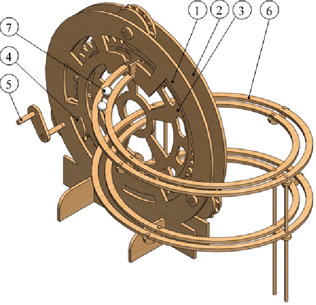
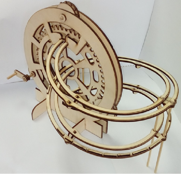
This notebook calculates translational velocity of ball’s center during rolling down the spiral path. Centripetal force acting on the ball increases own intensity with square of velocity and might cause ball to fall off. Analysis was shown that in the third part of spiral track inner reaction was become zero, so ball was in contact only with outer rail of track and was jumping out, so third part of spiral track needed to be fenced.
Definition of spiral path
Definition of spiral path
Three-dimensional spiral path for rolling ball parametrized by a variable which runs from to (two revolution helix spiral)
t
0
4π
Clear[t,x,y,z,P,Fi,Fo];(*lefthand,helixspiraltrack:dimensions120x120x160mm*)x[t_]=0.12*Cos[t];(*m*)y[t_]=0.12*Sin[t];(*m*)z[t_]=-*t;(*m;foursemicircleconsoles,deflectedby40mm*)P[t_]={x[t],y[t],z[t]};(*pointontrack*)curveplot=ParametricPlot3D[P[t],{t,0,4*3.14},PlotStyleThickness[0.01],PlotRangeAll,AxesLabel{"x, m","y, m","z, m"},ViewPoint{-1.3,2,1}]
0.04
π

Definition of unit vectors along the path in natural coordinate system
Definition of unit vectors along the path in natural coordinate system
For given a parameterized path r(t), definition of unit vectors in tangential, normal and binormal directions are:

r[t_]:=0.12*Cos[t],0.12*Sin[t],-*t(*path*)(*unitvectorsintangential,normalandbinormaldirectionsonthepath*)uT[t_]:=Simplify[r'[t]/Norm[r'[t]],t∈Reals];(*red*)vN[t_]:=Simplify[uT'[t]/Norm[uT'[t]],t∈Reals];(*blue*)vB[t_]:=Simplify[Cross[r'[t],r''[t]]/Norm[Cross[r'[t],r''[t]]],t∈Reals];(*green*)Curv[t_]:=SimplifyNorm[Cross[r'[t],r''[t]]],t∈Reals(*thecurveofthepath*)curveplot=ParametricPlot3D[P[t],{t,0,4*3.14},PlotStyleThickness[0.006],BoxedFalse];arT=Table[{P[t],P[t]+0.04*uT[t]},{t,0,4*3.14,1}];arN=Table[{P[t],P[t]+0.04*vN[t]},{t,0,4*3.14,1}];arB=Table[{P[t],P[t]+0.04vB[t]},{t,0,4*3.14,1}];SetOptions[Plot3D,BaseStyle->{FontFamily->"Times",FontSize12}];Show[curveplot,Graphics3D[{Red,Thick,Arrowheads[0.03],Arrow[arT],Gray,AbsolutePointSize@12,Point@arT[[All,1]]}],Graphics3D[{Blue,Thick,Arrowheads[0.03],Arrow[arN],Gray,AbsolutePointSize@12,Point@arN[[All,1]]}],Graphics3D[{Green,Thick,Arrowheads[0.03],Arrow[arB],Gray,AbsolutePointSize@12,Point@arB[[All,1]]}],PlotRangeAll,AxesLabel{"x ,m","y ,m","z ,m"},ViewPoint{-1.3,2,1}]
0.040
π
3
(Norm[r'[t]])

Ball' s center velocity calculated using energy conservation
Ball' s center velocity calculated using energy conservation
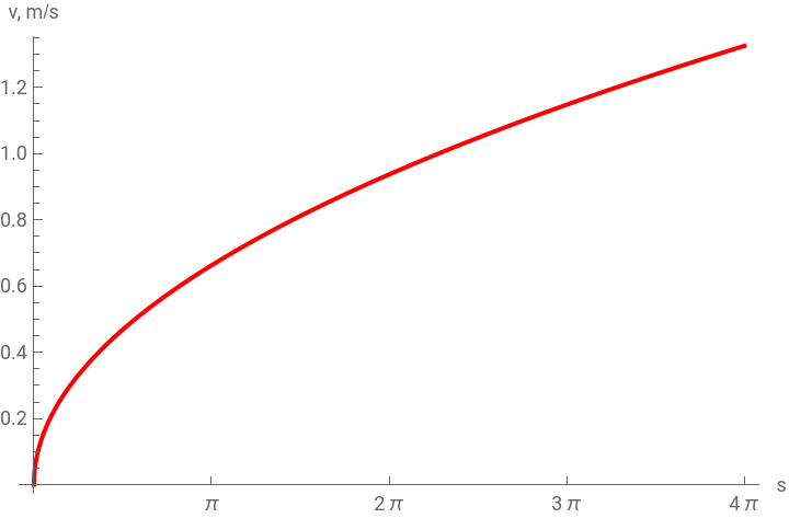
Velocity of ball can be calculated using energy conservation. The system is closed, so energy must be conserved. Initially the ball is at rest, so at this instant it contains only potential energy. When it travels along the track, it has potential energy and kinetic energy (translational and rotational). This part shows ball velocity as vectors drawn for certain points along the path and ball velocity intensity during descending.
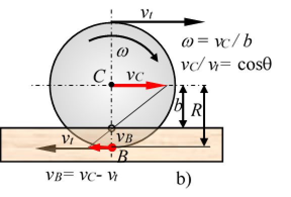

g=9.81;(*gravity,m/s^2*)R=0.0057;(*ballradius,m*)m=*7850;(*steelballmass,kg*)b=R*Cos[44.56Degree];(*bistheheightoftheballcenterfromthepointsofcontactwithtracks,m*)Ic=m*;(*momentofinertiaaboutball’scenterofmass,kg*m^2*)v[t_]:=**t;(*ball’scentervelocity,m/s*)curveplot=ParametricPlot3D[P[t],{t,0,4*3.14},PlotStyleThickness[0.007],BoxedFalse];arv=Table[{P[t],P[t]+0.1v[t]*uT[t]},{t,0,4*3.14,0.5}];Show[curveplot,Graphics3D[{Thick,Darker@Red,Arrowheads[0.03],Arrow[arv],Gray,AbsolutePointSize@12,Point@arv[[All,1]]}],PlotRangeAll,AxesLabel{"x,m","y,m","z,m"},ViewPoint{-1.3,2,0.8}]SetOptions[Plot,BaseStyle->{FontFamily->"Times",FontSize12}];Plot[{v[t]},{t,0,4*π},Ticks{{0,Pi,2Pi,3Pi,4Pi}},PlotStyle{Red,Thick},AxesLabel{"s","v, m/s"}]
4π*
3
R
3
2
5
2
R
2m*g
m+
Ic
2
b
0.04
π

Reaction on outside rail Fo and reaction on inside rail Fi
Reaction on outside rail Fo and reaction on inside rail Fi
Reaction on outside rail Fo increases due to increase of centripetal force. Opposite, reaction on inner rail Fi decreases and near the end (3/4) of third half-revolution it becomes zero. Because of this all third part of path was needed to be fenced as it can be seen on the right figure at the beginning.