Parallel and Counterflow Heat Exchangers
Parallel and Counterflow Heat Exchangers


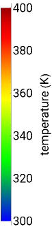
This Demonstration calculates temperatures and the rate of heat transfer in a concentric tube heat exchanger. The cold fluid is liquid water, which flows through the center of the heat exchanger. Select the hot fluid (air, liquid water, liquid sodium), which flows through the annular region, from the drop-down menu. Use buttons to select either parallel or counterflow. Set the length of the heat exchanger and the mass flow rates of the hot and cold fluids with sliders. Select "diagram" to show a schematic of the heat exchanger. Select "temperature plot" to show a plot of temperature versus distance through the heat exchanger for each stream. In both displays, colors represent the temperature (using the color scale on the right) and arrows indicate the direction of flow.
Details
Details
The temperatures of the hot stream and the cold stream of the heat exchanger are calculated from these differential equations:
T
h
T
c
C
h
T
h
z
d
i
T
h
T
c
for parallel flow:
C
c
T
c
z
d
i
T
h
T
c
for counterflow:
C
c
T
c
z
d
i
T
h
T
c
where =, is mass flow rate (kg/s), is heat capacity (J/[kg K]), is length down the heat exchanger (m), is the overall heat transfer coefficient () and is the inner diameter (m).
C
j
m
j
Cp
j
m
j
Cp
j
z
U
W/[K]
2
m
d
i
The overall heat transfer coefficient is calculated using the heat transfer coefficients of the cold and hot streams:
η
c
η
h
U=+
-1
1
η
c
1
η
h
The heat transfer coefficients are calculated from Nusselt correlations. The Reynolds number is:
Re
j
m
j
μ
j
d
j
where is the dynamic viscosity (), is the diameter (m) where is or for the cold or hot streams. The diameter of the tube that the cold fluid flows through is =, and the hydraulic diameter of the annulus that the hot fluid flows through is =-, where is the outer diameter.
μ
j
[Ns]/
2
m
d
j
j
c
h
d
c
d
i
d
h
d
o
d
i
d
o
For turbulent flow (>10000), the Dittus–Boelter correlation for the Nusselt number is used:
Re
j
Nu
j
4/5
Re
j
n
Pr
j
otherwise, =4.36 is used for laminar flow,
Nu
j
where = is the Prandtl number, is thermal conductivity (W/[m K]), for heating and for cooling.
Pr
j
Cp
j
μ
j
k
j
k
j
n=0.4
n=0.3
The heat transfer coefficients for each stream are calculated from =.
Nu
j
η
j
d
j
k
j
References
References
[1] T. L. Bergman, A. S. Lavine, F. P. Incropera and D. P. DeWitt, Introduction to Heat Transfer, 6th ed., Hoboken: John Wiley and Sons, 2011.
Permanent Citation
Permanent Citation
Rachael L. Baumann, John L. Falconer, Nathan S. Nelson
"Parallel and Counterflow Heat Exchangers"
http://demonstrations.wolfram.com/ParallelAndCounterflowHeatExchangers/
Wolfram Demonstrations Project
Published: May 2, 2016