Liquid crystal is a phase of matter that is in-between a crystalline solid and a liquid. The particles making up the material maybe highly oriented or can be in an amorphous state (figure1).
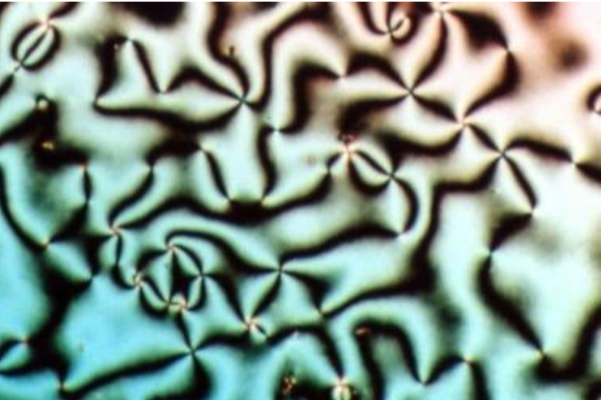
Figure1: Schlieren texture of liquid crystal nematic phase (Wikipedia)
Beyond its interest to physicists and material scientists, liquid crystals have found their place in numerous applications in recent decades, the most prominent being the Liquid Crystal Displays (LCD). A generation prior to the LED displays, LCDS could be found ubiquitously in all digital displays. The concept was simple, an internal impetus such as an electric signal could be used to change the orientation of the particles and therefore, affecting the polarization of light.
In my research with biological systems, we also consider a layer of confluent biological cells as an active form of liquid crystals since the cells in the tissue can move and change their orientation with respect to their neighbours. We define the orientational order in liquid crystals with nematic directors (vectors in space depicting a bulk or local orientation of molecules). There can be defects within the orientational order also known as nematic defects. Such defects are computed from the nematic directors and are usually represented as integers or fraction terms, based on the computation of winding numbers of nematic directors. Most common defects are +1, -1 and +1/2 and -1/2 defects (see figure 2). Interestingly, human fingerprint patterns also have orientational or nematic defects (refer yet again to figure 2).
In my research with biological systems, we also consider a layer of confluent biological cells as an active form of liquid crystals since the cells in the tissue can move and change their orientation with respect to their neighbours. We define the orientational order in liquid crystals with nematic directors (vectors in space depicting a bulk or local orientation of molecules). There can be defects within the orientational order also known as nematic defects. Such defects are computed from the nematic directors and are usually represented as integers or fraction terms, based on the computation of winding numbers of nematic directors. Most common defects are +1, -1 and +1/2 and -1/2 defects (see figure 2). Interestingly, human fingerprint patterns also have orientational or nematic defects (refer yet again to figure 2).
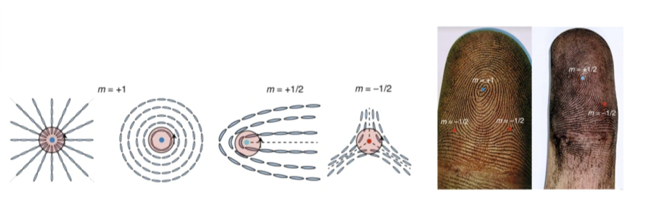
Figure 2: (left) most common nematic defects in liquid crystals (right) human fingerprints marking places of nematic defects
In the context of cell and developmental biology these defects pertain to certain process such as cell migration, cell death or apoptosis and a cell extruding amongst other cells ( figure 3, adapted from https://www.nature.com/articles/nature21718 ).
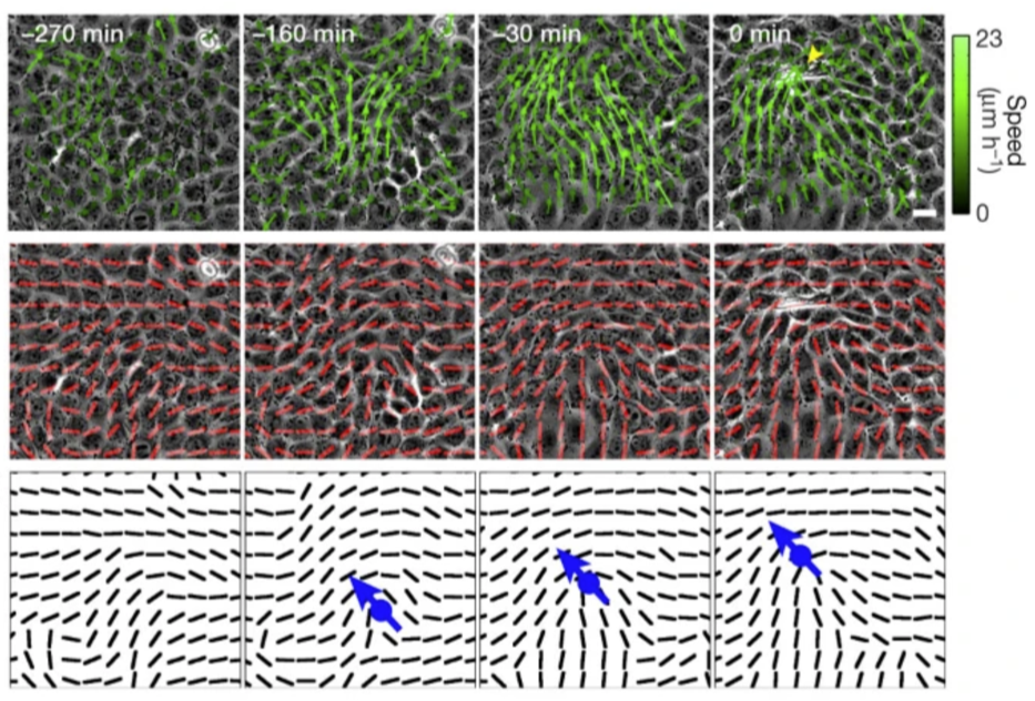
Figure 3: (top panel) motion of biological cells in a tissue computed with PIV (middle panel) nematic directors superimposed on the biological tissue (3) +1/2 defect is visibly moving in space as the cells move across the tissue.
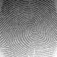
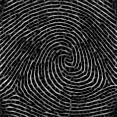
Most recently, for a project that I had been working on, I implemented a code in Wolfram Language to compute orientational order and infer nematic defects in a layer of biological tissue. Below, I take example of a simple human figure print to detail how these nematic defects can be found. Needless to say, my choice of Wolfram Language makes it seamlessly easy to express and implement what is on my mind. I implemented two different methods via which the nematic defects can be detected.
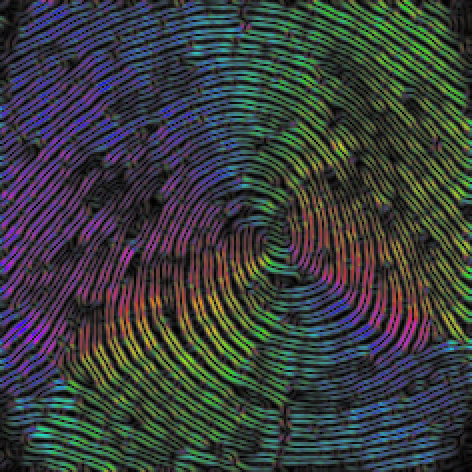
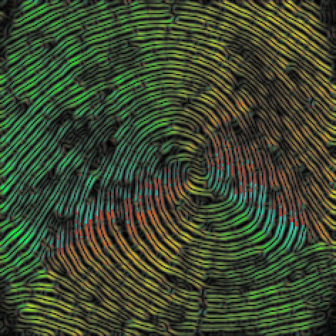
In essence, the common theme in both methods is that I compute the intensity gradients of the image in the x-axis and the y-axis to determine the orientational angle of the intensity gradient. In the first method, I explicitly use the nematic directors to compute the winding number to detect the integer and fractional defect. This method apparently is more robust in my opinion. In the second method, I find sharp changes in the orientational angle of the intensity gradient, which are the hallmarks of locations of nematic defects.
In essence, the common theme in both methods is that I compute the intensity gradients of the image in the x-axis and the y-axis to determine the orientational angle of the intensity gradient. In the first method, I explicitly use the nematic directors to compute the winding number to detect the integer and fractional defect. This method apparently is more robust in my opinion. In the second method, I find sharp changes in the orientational angle of the intensity gradient, which are the hallmarks of locations of nematic defects.
Full code ahead.
Method 1: from the director field
Method 1: from the director field
In[]:=
ClearAll["Global`*"];
In[]:=
Clear[imageOrientationFn];imageOrientationFn[image_,rad_]:=Block{gy,gx,kernel1={1,0},kernel2={0,1},orientationParallel,orientationPerp},gy=GaussianFilter[image,rad,kernel1];gx=GaussianFilter[image,rad,kernel2];orientationParallel=ArcTan[((gy*gy)-(gx*gx)),2(gx*gy)];orientationPerp=ArcTan[Sin[orientationParallel],-Cos[orientationParallel]];{orientationParallel,orientationPerp};
1
2
In[]:=
ClearAll@fnComp;Block{v1,v2,m,ang},fnComp=Compile{{vec1,_Real,1},{vec2,_Real,1}},v1=vec1;v2=vec2;ang=ArcTan[v1.v2,Abs[Det[{v1,v2}]]];Ifang>,v2*=-1;m=Det[{v1,v2}];ang=Sign[m]ArcTan[v1.v2,Abs@m],RuntimeOptions->"Speed",CompilationTarget->"C",CompilationOptions->{"ExpressionOptimization"->True}
N[π]
2.0
Out[]=
CompiledFunction


In[]:=
i=
;ImageAdjust[r=RidgeFilter[i,2]]magnitude=ImageAdjust[Sqrt[GaussianFilter[r,2,{1,0}]^2+GaussianFilter[r,2,{0,1}]^2]];{orientationparallel,orientationperp}=imageOrientationFn[r,1];{ColorCombine[{ImageAdjust@orientationparallel,magnitude,magnitude},"HSB"],ColorCombine[{ImageAdjust@orientationperp,magnitude,magnitude},"HSB"]}
Out[]=
Out[]=
,
In[]:=
imgpartitions=ImagePartition[orientationparallel,25]
Out[]=
{{
,

,

,

,

,

,

,

,

},{

,

,

,

,

,

,

,

,

},{

,

,

,

,

,

,

,

,

},{

,

,

,

,

,

,

,

,

},{

,

,

,

,

,

,

,

,

},{

,

,

,

,

,

,

,

,

},{

,

,

,

,

,

,

,

,

},{

,

,

,

,

,

,

,

,

},{

,

,

,

,

,

,

,

,

}}

In[]:=
imgpartdim=Dimensions[imgpartitions];
In[]:=
directorfield=ParallelTableθ=Flatten[ImageData[part]];=Γ=θ[[p]];{Λ,Π}=N[{Cos[Γ],Sin[Γ]}];
-
;{eigvals,eigvecs}=Eigensystem[];First@Extract[eigvecs,Position[eigvals,Max@eigvals]],{part,Flatten@imgpartitions};
Q
αβ
Length[θ]
∑
p=1
3
2
2 Λ | ΛΠ |
ΛΠ | 2 Π |
1
2
1 | 0 |
0 | 1 |
Q
αβ
In[]:=
parts=Partition[directorfield,Sequence@@imgpartdim];assoc=<|Rule@@@Flatten[{Array[{##}&,imgpartdim],parts},{3,2}]|>;keys=Keys[assoc];keystrunc=DeleteCases[keys,{1|imgpartdim[[1]],_}|{_,1|imgpartdim[[1]]}];neighbours={{0,1},{0,-1},{-1,0},{1,0},{-1,1},{-1,-1},{1,1},{1,-1}};neighbourparts={{neighbours[[1]],neighbours[[5]]},{neighbours[[5]],neighbours[[3]]},{neighbours[[3]],neighbours[[6]]},{neighbours[[6]],neighbours[[2]]},{neighbours[[2]],neighbours[[8]]},{neighbours[[8]],neighbours[[4]]},{neighbours[[4]],neighbours[[7]]},{neighbours[[7]],neighbours[[1]]}};keypairings=Map[keystrunc[[10]]+#&,neighbourparts,{2}];
Method 2: sudden or sharp changes in orientation field
Method 2: sudden or sharp changes in orientation field
CITE THIS NOTEBOOK
CITE THIS NOTEBOOK
Finding orientational defects from images of fingerprints and materials
by Ali Hashmi
Wolfram Community, STAFF PICKS, October 11, 2023
https://community.wolfram.com/groups/-/m/t/3032057
by Ali Hashmi
Wolfram Community, STAFF PICKS, October 11, 2023
https://community.wolfram.com/groups/-/m/t/3032057