When modular robots are treated as systems of 2D unit squares, their possible movements and resulting configurations can be modelled using multiway graphs in order to find the optimal path between two configurations. The properties of the resulting multiway graphs can be further analyzed to make observations about the movement of modular robots, such as their flexibility and number of resulting configurations when there is a change in the number of modules or restrictions to movement.
Introduction
Introduction
Traditional robotics treated a robot as a single fixed-purpose machine. Robots involved one body, one set of actuators, and a design for one class of tasks. Modular robotics altered the traditional expectation of robots by framing them as interconnected, distributed system, changing the societal perspective of robotics as a whole.
The applications of modular robots extend beyond the range of traditional robotics in a variety of fields. This project aimed to use multiway graphs to model the movements of modular robots, identify the most optimal path to reach an end configuration from a starting configuration, and analyze the properties of graphs produced.
The applications of modular robots extend beyond the range of traditional robotics in a variety of fields. This project aimed to use multiway graphs to model the movements of modular robots, identify the most optimal path to reach an end configuration from a starting configuration, and analyze the properties of graphs produced.
Computationally Describing Modules and 90° Rotations
Computationally Describing Modules and 90° Rotations
Computationally Describing Modular Robotic Systems
Computationally Describing Modular Robotic Systems
In order to model movements of modular robots, I first identified a method to computationally describe modules. I began with the 2D case of modular robots by observing 90 degree rotations of squares along connecting turning points.
I represented the robot as a connected configuration of unit square modules. Two modules are considered adjacent if they share either a common edge or a common vertex. Modules, which are unit squares, can be described using the coordinate points of their centers. A configuration of modules, inputted as a list of coordinates, appears as one vertex in the overall multiway graph.
To visualize these systems, I plotted these points on a Cartesian plane to create patterns of squares.
The following function takes in a list of center coordinates as input and visualizes their modular configuration.
In[]:=
drawConfig[coordList_]:=Graphics[Inset[Graphics[{EdgeForm[{Blue}],White,Rectangle[]}],{#1-.5,#2-.5},Center,{1,1}]&@@@coordList,ImageSize->10*{Max[coordList[[All,1]]]-Min[coordList[[All,1]]]+1,Max[coordList[[All,2]]]-Min[coordList[[All,2]]]+1}]
In[]:=
drawConfig[{{3,5},{2,5},{2,4}}]
Out[]=
Computationally Describing 90° Rotations
Computationally Describing 90° Rotations
Before allowing rotations of modules to occur, it was necessary to define the criteria for a successful rotation. This criteria can be formulated by observing the behavior of modules as they rotate and interact with one another. The criteria for 90° rotations to occur are that a rotation cannot cause a collision between modules and cannot result in a disconnected system.
Collisions Between Modules
Collisions Between Modules
For a given counter-clockwise or clockwise rotation around a corner joining two modules, a turn is not possible if it will result in a collision between modules during the rotation or after it occurs.
For example, the rotation below is a clockwise rotation of the Northwest corner of the center module. Assuming that the center of the rotating module lies at the coordinate point {0,0}, this rotation is not legal under the conditions that the points {-1,0}, {-1,-1}, and {0,-1} also exist within the system.
For example, the rotation below is a clockwise rotation of the Northwest corner of the center module. Assuming that the center of the rotating module lies at the coordinate point {0,0}, this rotation is not legal under the conditions that the points {-1,0}, {-1,-1}, and {0,-1} also exist within the system.
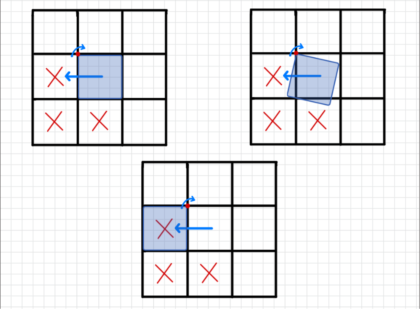
I recorded the surrounding modules that would not allow each rotation. Computationally, observing this criterion involves checking all coordinate points within the system to ensure that the rotating block will not collide with any other points.
The following function treats individual modules as vertices and checks whether they form a weakly connected graph to ensure that they form a modular robotic system.
In[]:=
connectedConfigQ[newconfig_]:=WeaklyConnectedGraphQ[RelationGraph[EuclideanDistance[#1,#2]<1.5&,newconfig]]
Eight Possible Rotations
Eight Possible Rotations
The eight possible rotations of a module include counterclockwise and clockwise rotations along each of the four corners of a unit square. Using the above criteria, I defined functions that checked which rotations were possible for a rotating square in a given configuration. These functions can be demonstrated using an example configuration, {{3,5},{2,5},{2,4}} when {3,5} is the rotating module.
In[]:=
drawConfig[{{3,5},{2,5},{2,4}}]
Out[]=
When each of the following functions are given a configuration with the specification of the rotating square, it returns the resulting configuration if the rotation is possible.
Find a possible clockwise turn about the NW corner.
In[]:=
possibleTurnNWclockwise[{x_,y_},config_]:=With[{newConfig=Replace[config,{x,y}->{x-1,y},{1}]},If[And[Not[IntersectingQ[{{x-1,y},{x,y-1},{x-1,y-1}},config]],connectedConfigQ[newConfig]],newConfig,Null]]
In[]:=
possibleTurnNWclockwise[{3,5},{{3,5},{2,5},{2,4}}]
A clockwise rotation of {3,5} along the Northwest corner is not legal because it translates 1 unit leftwards, taking the place of {2,5}.
Find a possible counterclockwise turn about the NW corner.
In[]:=
possibleTurnNWcounterclockwise[{x_,y_},config_]:=With[{newConfig=Replace[config,{x,y}->{x,y+1},{1}]},If[And[Not[IntersectingQ[{{x,y+1},{x+1,y+1},{x+1,y}},config]],connectedConfigQ[newConfig]],newConfig,Null]]
A counterclockwise rotation of {3,5} along the Northwest corner is legal and produces the following configuration.
In[]:=
drawConfig[possibleTurnNWcounterclockwise[{3,5},{{3,5},{2,5},{2,4}}]]
Out[]=
Find a possible clockwise turn about the SW corner.
In[]:=
possibleTurnSWclockwise[{x_,y_},config_]:=With[{newConfig=Replace[config,{x,y}->{x,y-1},{1}]},If[And[Not[IntersectingQ[{{x+1,y},{x,y-1},{x+1,y-1}},config]],connectedConfigQ[newConfig]],newConfig,Null]]
A clockwise rotation of {3,5} along the Southwest corner is legal and produces the following configuration.
In[]:=
drawConfig[possibleTurnSWclockwise[{3,5},{{3,5},{2,5},{2,4}}]]
Out[]=
Find a possible counterclockwise turn about the SW corner.
In[]:=
possibleTurnSWcounterclockwise[{x_,y_},config_]:=With[{newConfig=Replace[config,{x,y}->{x-1,y},{1}]},If[And[Not[IntersectingQ[{{x,y+1},{x-1,y+1},{x-1,y}},config]],connectedConfigQ[newConfig]],newConfig,Null]]
A counterclockwise rotation of {3,5} along the Southwest corner is not legal because it collides with {2,5}.
In[]:=
possibleTurnSWcounterclockwise[{3,5},{{3,5},{2,5},{2,4}}]
Find a possible clockwise turn about the NE corner.
In[]:=
possibleTurnNEclockwise[{x_,y_},config_]:=With[{newConfig=Replace[config,{x,y}->{x,y+1},{1}]},If[And[Not[IntersectingQ[{{x,y+1},{x-1,y+1},{x-1,y}},config]],connectedConfigQ[newConfig]],newConfig,Null]]
A clockwise rotation of {3,5} along the Northeast corner is not legal because it collides with {2,5}.
In[]:=
possibleTurnNEclockwise[{3,5},{{3,5},{2,5},{2,4}}]
Find a possible counterclockwise turn about the NE corner.
In[]:=
possibleTurnNEcounterclockwise[{x_,y_},config_]:=With[{newConfig=Replace[config,{x,y}->{x+1,y},{1}]},If[And[Not[IntersectingQ[{{x+1,y},{x,y-1},{x+1,y-1}},config]],connectedConfigQ[newConfig]],newConfig,Null]]
A counterclockwise rotation of {3,5} along the Northeast corner is not legal because it results in a disconnection.
In[]:=
possibleTurnNEcounterclockwise[{3,5},{{3,5},{2,5},{2,4}}]
Find a possible clockwise turn about the SE corner.
In[]:=
possibleTurnSEclockwise[{x_,y_},config_]:=With[{newConfig=Replace[config,{x,y}->{x+1,y},{1}]},If[And[Not[IntersectingQ[{{x+1,y},{x,y+1},{x+1,y+1}},config]],connectedConfigQ[newConfig]],newConfig,Null]]
A clockwise rotation of {3,5} along the Southeast corner is not legal because it results in a disconnection.
In[]:=
possibleTurnSEclockwise[{3,5},{{3,5},{2,5},{2,4}}]
Find a possible counterclockwise turn about the SE corner.
In[]:=
possibleTurnSEcounterclockwise[{x_,y_},config_]:=With[{newConfig=Replace[config,{x,y}->{x,y-1},{1}]},If[And[Not[IntersectingQ[{{x,y-1},{x-1,y},{x-1,y-1}},config]],connectedConfigQ[newConfig]],newConfig,Null]]
A counterclockwise rotation of {3,5} along the Southeast corner is not legal because it collides with {2,5} and {2,4}.
The following function sorts the modules of a given configuration into lexicographic order by coordinates of each block’s center, then shifts the entire configuration so that the first block is centered at the origin, to aid in judging whether two configurations are the same.
The following function finds all configurations resulting from clockwise turns of a given square, and canonicalizes the results.
The following function finds all configurations resulting from counterclockwise turns of a given square, and canonicalizes the results.
The following function finds all configurations resulting from all turns of a given square, and canonicalizes the results.
Creating Graphs to Model Rotations
Creating Graphs to Model Rotations
Updating Vertices/Creating Graph
Updating Vertices/Creating Graph
In order to create the multiway graph of all possible resulting configurations, the code follows the following logic: given some configuration and one of its square modules, consider each possible adjacent configuration created by rotating that square. If the configuration is new, a new vertex is added to the multiway graph, with an edge directed from the current configuration to the new one. If the configuration is not new, an edge directed from the current configuration to the existing one is added. The function repetitively checks the first element of a list of unprocessed configurations in order to conduct this analysis. This process repeats until there are no more possible resulting configurations and the list is empty.
The following function takes a current graph and list of configurations as input and returns an updated graph and list of configurations.
The following function creates the complete directed multiway graph for a given connected configuration by iteratively generating every reachable configuration, then displays the resulting graph with labelled vertices.
Create a multiway graph.
Visualizing Paths Through the Multiway Graph
Visualizing Paths Through the Multiway Graph
Create a multiway graph.
Select two of its vertices.
Find a shortest path between them.
Animate the path.
Testing and Analysis of Graph Properties
Testing and Analysis of Graph Properties
Isomorphism
Isomorphism
For a fixed number of n squares, the multiway graphs generated from different initial configurations appear to be isomorphic. This can be investigated by constructing the transformation graph for configurations consisting of 2–6 squares and comparing the resulting graphs.
n=2
n=3
n=4
n=5
n=6
Restricting to Counter-clockwise/Clockwise Turns with Changes in n
Restricting to Counter-clockwise/Clockwise Turns with Changes in n
To investigate how restrictions on movement affect the reconfiguration of modular robots, I compared the state-space graphs produced when turns are unrestricted in both directions and when turns are only allowed in the counter-clockwise direction.
Considering that configurations with an equal n number of squares yield isomorphic state space graphs, I observed the impact of changing n on various metrics. I compared graphs ranging from n = 2 to n = 6 using their unrestricted case and counter-clockwise restricted case.
Considering that configurations with an equal n number of squares yield isomorphic state space graphs, I observed the impact of changing n on various metrics. I compared graphs ranging from n = 2 to n = 6 using their unrestricted case and counter-clockwise restricted case.
Visualization of Metrics
Visualization of Metrics
As n increases, the set of reachable configurations of a graph increases approximately exponentially.
Visualize the change in reachable configurations as n increases for a graph with unrestricted turns.
Visualize the change in reachable configurations as n increases for a graph with only counter-clockwise turns.
As the number of squares increases, the number of reachable configurations grows rapidly, showing that the robot’s state space expands with its size. The unrestricted and counterclockwise-only graphs have identical vertex counts for every value of n, indicating that restricting the robot to only counterclockwise turns does not reduce the set of configurations that can eventually be reached.
As n increases, the number of possible transitions increases. The unrestricted graph contains substantially more edges than the counterclockwise-only graph, and this gap grows as n increases. While both movement rules experience an increase in edge count as n increases, restricting the robot removes a large number of direct transitions.
The average out-degree increases with the number of squares for both movement rules, indicating that larger robots have more possible moves from any given configuration. The unrestricted graph consistently has roughly twice the average out-degree of the restricted graph, which means that allowing both turning directions improves the robot’s local flexibility by giving it more immediate options at each step.
The graph diameter increases as the robot becomes larger, showing that more turns are required in the worst case to transform between two configurations. The diameter is consistently larger for the counterclockwise-only graph, indicating that movement restrictions cause the robot to take longer reconfiguration paths.
The ratio of transitions in the counterclockwise-restricted graph to the unrestricted graph remains approximately 0.5 for all tested values of n. This shows that restricting the robot to counterclockwise turns removes roughly half of the possible one-turn reconfiguration moves, as expected since clockwise moves are no longer permitted. The slight increase above 0.5 for larger values of n is likely due to configurations in which some clockwise moves are already impossible because of geometric constraints.
The ratio of average outdegree in counterclockwise-restricted graphs to unrestricted graphs remains approximately 0.5 for all tested values of n. Since average out-degree is {Average Out Degree = Edge Count/Vertex Count}, this result is consistent with the previous graph, considering that vertex count is equal in both the restricted and unrestricted graph for all tested values of n. On average, each configuration retains only about half as many legal moves when clockwise turns are prohibited.
Applications
Applications
A primary objective of mine was to use my observations about state-space graphs of unit-square configurations to aid engineers in creating and moving optimal modular robots. The bar chart pictured below may allow users to compare the mobility and flexibility of different starting configurations.
The following function constructs the state-space graph for a given starting configuration and displays a bar chart showing how many configurations are reachable after n number of turns from the starting configuration.
Conclusion
Conclusion
This project developed a method for generating a complete multiway graph of all reachable configurations of a modular robot from an arbitrary starting configuration. Analysis of the resulting graphs showed that restricting the robot to only clockwise or counterclockwise turns reduces the number of legal transitions between configurations, decreases the robot’s local flexibility, and increases the maximum number of turns required to travel between configurations, while still maintaining the set of reachable configurations. As the number of robot modules increased, the state-space graph grew approximately exponentially. Finally, the increase in maximum betweenness centrality and decrease in average closeness centrality as n increased showed that larger robots rely more on key intermediate configurations and generally require more reconfiguration steps to reach other states. These results demonstrate how graph-theory metrics can be used to evaluate the efficiency of modular robotic reconfiguration.
Future Directions
Future Directions
There are several opportunities to extend this work in the future. The current model could be expanded from two-dimensional square modules to three-dimensional cubic modules, which would better represent the movement of modular robots. I would also like to investigate more graph properties in further detail to make more robust observations about modular robot configurations. Finally, I would like to further prove conjectures made throughout this essay.
Acknowledgements
Acknowledgements
I would like to thank Dan McDonald, my mentor, for his unwavering guidance and support throughout my project. I would like to thank Joseph Brennan, my advocate, for helping me explore different interests and pathways for my project. I would like to thank Divya Thota and Amrita Kumar for helping me debug my code. I would like to thank Eryn Gillam, Rory Foulger, and Megan Davis, our program directors, making this program possible. Finally, I would like to thank Stephen Wolfram for providing me with this exhilarating project idea.
CITE THIS NOTEBOOK
CITE THIS NOTEBOOK
Modelling the movement of modular robots using multiway graphs
by Fiza Mehfil
Wolfram Community, STAFF PICKS, July 9, 2026
https://community.wolfram.com/groups/-/m/t/3753413
by Fiza Mehfil
Wolfram Community, STAFF PICKS, July 9, 2026
https://community.wolfram.com/groups/-/m/t/3753413