This notebook was created in collaboration with Enrico Babilio and Rana Nazifi Charandabi
ABSTRACT (original article): This work presents a tensegrity design approach for a small-to-medium-sized sports stadium, equipped with sun-tracking solar modules on its roof. A novel V-Expander unit is used to create a modular roof structure, with members optimized using a minimal mass strategy. The stability of the entire stadium structure and the deflections of the cantilever roof are analyzed under vertical, seismic, and wind loads through detailed finite element analysis. Electrical power production is estimated over one year for the Salerno area. The results demonstrate that the tensegrity solar roof exhibits limited deflections and remarkable solar energy harvesting capabilities, utilizing sun-tracking strategies tailored to different sectors of the grandstands. This research paves the way for the design of multi-scale sports stadiums featuring sustainable, adaptive lightweight tensegrity structures. These systems employ sun-tracking photovoltaic modules that can be tilted by simply wrapping a bus cable around a winch. CITATION (original article): Nazifi Charandabi, R., Babilio, E., Carpentieri, G., Spagnuolo,G., Amendola, A., Fraternali, F., A tensegrity structure for a solar stadium roof with sun-tracking capability, Thin-Walled Structures 210, 2025, 113033. https://doi.org/10.1016/j.tws.2025.113033
Introduction
Introduction
Architects, engineers, and sports agencies have been working for over 20 years to enhance the sustainability of sports stadiums and reduce their energy consumption and carbon footprint, which are typically very high. A remarkable number of sports stadiums equipped with photo voltaic (PV) panels (solar-powered stadiums) have been designed and built in recent years. However, it appears that no examples of stadium roofs with sun-tracking PV panels have been realized to date. In the tensegrity design of a novel solar stadium structure with sun-tracking capabilities is illustrated.The examined stadium roof structure tessellates the tensegrity unit illustrated below (graph reproduced without changes from ,under CC BY-NC-ND 4.0 license), to form the roof elements of the grandstand structures described in the following sections.
[1]
[1]
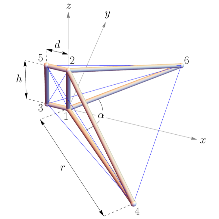
The used tensegrity unit is a variant of the original V-Expander, introduced by René Motro in his well-known textbook as a V-shaped system composed of eight bars arranged in two distinct sets of four bars each, with equal lengths. The bars are connected by one vertical cable, along with eight horizontal and eight diagonal cables. The variant used is a class-4 tensegrity structure composed of eight bars and seven cables, featuring a vertical quadrangular section with height h and width d, formed by nodes 1, 2, 3, and 5. The system is completed by one base triangle (1, 4, 6) lying in a horizontal plane and a sloped triangle (2, 4, 6). The “arms” 1-4 and 1-6 lie on a circle with radius r, centered at node 1. The module is employed to create a cantilever roof structure by arranging an array of modules along the y-axis, which is perpendicular to the x-axis aligned with the bar 1-3. Such a module does not exhibit infinitesimal mechanisms. We set the origin of the (x,y,z) Cartesian coordinate system at node 1. It is worth noting that the V-Expander module designed for minimal mass is modeled as an independent structure with restraint conditions to simplify its interactions with adjacent parts of the grandstand structures. It is restrained by fixing node 3, constraining nodes 1, 2, and 5 in the longitudinal y-direction, and additionally constraining node 1 in the vertical z-direction aligned with the bar 1-2. The tensegrity stadium concept assumes the y-axis is parallel to one edge of the grandstands, which form a sports stadium structure with a rectangular plan.
[2]
Code to draw the V-Expander module shown above
Code to draw the V-Expander module shown above
In[]:=
Oxyz={0,0,0};height=5;span=2;armlength=12;angle=;radbar=0.2;radnode=1.25radbar;pn[1]={0,0,0};pn[2]={0,0,height};pn[3]={-span,0,0};pn[4]=armlengthCos,-armlengthSin,0;pn[5]={-span,0,height};pn[6]=armlengthCos,armlengthSin,0;VExpander=Graphics3D[{{Sphere[{pn[1],pn[2]},radnode],Sphere[{pn[5],pn[3]},radnode],Sphere[{pn[1],pn[4]},radnode],Sphere[{pn[1],pn[6]},radnode],Sphere[{pn[2],pn[4]},radnode],Sphere[{pn[2],pn[6]},radnode],Sphere[{pn[2],pn[5]},radnode],Sphere[{pn[1],pn[3]},radnode]},{LightBrown,Tube[{pn[1],pn[2]},radbar],Tube[{pn[5],pn[3]},radbar],Tube[{pn[1],pn[4]},radbar],Tube[{pn[1],pn[6]},radbar],Tube[{pn[2],pn[4]},radbar],Tube[{pn[2],pn[6]},radbar],Tube[{pn[2],pn[5]},radbar],Tube[{pn[1],pn[3]},radbar]},{Blue,Line[{pn[2],pn[3]}],Line[{pn[3],pn[4]}],Line[{pn[4],pn[6]}],Line[{pn[6],pn[3]}],Line[{pn[4],pn[5]}],Line[{pn[5],pn[6]}],Line[{pn[5],pn[1]}]}},BoxRatiosAutomatic,BoxedFalse,ViewPoint{1.2,-2.6,1.8},ImageSize650]
π
2
angle
2
angle
2
angle
2
angle
2
Out[]=

Code to draw the soccer field and the roof panels
Code to draw the soccer field and the roof panels
Geometric data
Geometric data
In[]:=
d=span;h=height;r=armlength;αpaper=angle;ell=rCos;p=+;L$=2rSin;evec[i_]:=IdentityMatrix[3]〚i〛;
angle
2
2
ell
2
h
angle
2
PV panels data
PV panels data
Soccer field measurements
Soccer field measurements
The roof panels
The roof panels
The soccer field
The soccer field
A view of the soccer field and and the roof panels
A view of the soccer field and and the roof panels
Code to draw movable roof panels
Code to draw movable roof panels
Rodrigues’ formula
Rodrigues’ formula
Major rotation axes (one-axis tracking)
Major rotation axes (one-axis tracking)
Minor rotation axes (two-axes tracking ready)
Minor rotation axes (two-axes tracking ready)
Rotated vectors and panels
Rotated vectors and panels
The role of master to four triangles is assigned
The role of master to four triangles is assigned
A view of the soccer field and and the roof panels with “manually” operated motion
A view of the soccer field and and the roof panels with “manually” operated motion
The movement of the roof pitches can be explored by moving the slider controls.
Sun data
Sun data
As in [4], the sun path and solar irradiance data for the examined days were obtained using PVLib v0 .10.3, a Python toolbox designed to simulate the performance of photovoltaic (PV) systems [5].
Here, however, only Mathematica commands are used.
Here, however, only Mathematica commands are used.
Decimal latitude and longitude (Salerno area) and example day (summer solstice)
Decimal latitude and longitude (Salerno area) and example day (summer solstice)
Sun path data
Sun path data
Maximization
Maximization
Centroids and unit normal vectors
Centroids and unit normal vectors
Computation of the optimal tilting angle
Computation of the optimal tilting angle
For the one-axis tracking, φ is held fixed, while θ is optimized.
Results
Results
The variation of the secondary (i.e. additional) tilting angles θ during the daylight hours is shown according the following color coding:
(i) N grandstand roof: solid blue line;
(ii) E grandstand roof: dot-dashed black line;
(iii) S grandstand roof: solid red line;
(iv) W grandstand roof: dashed gray line.
(i) N grandstand roof: solid blue line;
(ii) E grandstand roof: dot-dashed black line;
(iii) S grandstand roof: solid red line;
(iv) W grandstand roof: dashed gray line.
Roof pitches motion
Roof pitches motion
Resampling to reduce the number of animation frames
Resampling to reduce the number of animation frames
Current configuration of the roof panels
Current configuration of the roof panels
Current unit normal vectors
Current unit normal vectors
Position of the sun in the sky
Position of the sun in the sky
Some movie editing
Some movie editing
The movie shows the tracking of the sun during daylight hours, from sunrise to sunset.
As the sun rises, the roof tilts from the resting configuration, maintained during the night, to the optimal configuration.
The latter is adjusted during daylight hours.
At sunset, the roof returns to the rest configuration.
As the sun rises, the roof tilts from the resting configuration, maintained during the night, to the optimal configuration.
The latter is adjusted during daylight hours.
At sunset, the roof returns to the rest configuration.
Optimized motion during daylight hours
Optimized motion during daylight hours
Sunrise adjustments
Sunrise adjustments
Sunset adjustments
Sunset adjustments
The motion of the roof pitches from sunrise to sunset
The motion of the roof pitches from sunrise to sunset
Conclusions
Conclusions
This Mathematica notebook reports part of the code used in the study of a tensegrity roof of a small-to-medium-scale stadium with a capacity of nearly 10 000 seats. The roof is designed to be employed for solar energy harvesting by exploiting sun-tracking capabilities. In this study, the roof panels of the various grandstand sections are designed to tilt at distinct angles, maintaining uniform tilting within each section (one-axis tracking). With such a strategy a remarkable peak electrical power output can be achieved, reaching up to 510 kW when using thin-film solar panels with 18% power conversion efficiency. An additional, under investigation, improvement considers further optimization by allowing the individual modules forming the roofs of the grandstand sections to exhibit different tilting angles, incorporating two-axis tracking.
References
References
[1] R. Nazifi Charandabi, E. Babilio, G. Carpentieri, G. Spagnuolo, A. Amendola, F. Fraternali, “A tensegrity structure for a solar stadium roof with sun-tracking capability”. Thin-Walled Structures, 210, 2025, 113033. https://doi.org/10.1016/j.tws.2025.113033
[2] R. Motro, Tensegrity: Structural Systems for the Future, Butterworth-Heinemann, © 2003 Elsevier Ltd. https://doi.org/10.1016/B978-1-903996-37-9.X5028-8
[3] J. S. Dai, “Euler–Rodrigues formula variations, quaternion conjugation and intrinsic connections”. Mechanism and Machine Theory 2015, 92, 144–152. https://doi.org/10.1016/j.mechmachtheory.2015.03.004
[4] F. Fraternali, E. Babilio, R. Nazifi Charandabi, G. Germano, R. Luciano, G. Spagnuolo, “Dynamic origami solar eyes with tensegrity architecture for energy harvesting Mashrabiyas”, Applications in Engineering Science, 19, 2024,100190. https://doi.org/10.1016/j.apples.2024.100190
[5] W. Holmgren, K. Anderson, C. Hansen, Robwandrews, M. Mikofski, A.R. Jensen, A. Lorenzo, U. Krien, Bmu, A. Driesse, C. Stark, DaCoEx, M.S. de León Peque, T. Transue, E. Luis, Kt, N. Priyadarshi, Mayudong, Heliolytics, E. Miller, M.A. Anoma, V. Guo, L. Boeman, J. Stein, S. Jane, W. Vining, Jforbess, T. Lunel, C. Leroy, A. Morgan, “pvlib/pvlib-python: v0 .10.3”, 2023, Zenodo. http://dx.doi.org/10.5281/zenodo.10412885
CITE THIS NOTEBOOK
CITE THIS NOTEBOOK
A tensegrity structure for a solar stadium roof with sun-tracking capability
by Rana Nazifi Charandabi, Enrico Babilio, Gerardo Carpentieri, Giovanni Spagnuolo, Ada Amendola & Fernando Fraternali
Wolfram Community, STAFF PICKS, February 19, 2025
https://community.wolfram.com/groups/-/m/t/3396614
by Rana Nazifi Charandabi, Enrico Babilio, Gerardo Carpentieri, Giovanni Spagnuolo, Ada Amendola & Fernando Fraternali
Wolfram Community, STAFF PICKS, February 19, 2025
https://community.wolfram.com/groups/-/m/t/3396614