Understanding Refraction of Light
Determining the path of a light ray through different media to find the apparent position of an object
Author: Andrea Houck and Bhubanjyoti Bhattacharya
Determining the path of a light ray through different media to find the apparent position of an object
Author: Andrea Houck and Bhubanjyoti Bhattacharya
This essay discusses light traveling from one point in one medium to another point in another medium. We show first, how to find the potential light ray paths, then how to determine the allowed path by calculating the Euclidean optical path and finding the extremum with a single surface of interface. We verify the path follows Snell’s Law. We then create a final figure that shows the light path as the index of refraction of both media 1 and 2, the x and y coordinates of both points A and B, and the location of the surface of interface are manipulated. We include an application of this process as an observer viewing a fish in a pool of water from above. Following the same process, we add a second ray of light. We allow for manipulable input for the observer’s eye aperture in addition to the manipulable position. From this and the fixed actual position of the fish, we determine the fish’s apparent position. This situation is analyzed using single-surface refraction techniques since light from the fish passes through two media - water and air. We then expand our methods to investigate refraction with two surfaces. We follow a similar approach as with single-surface refraction where we first show how to find the potential light ray paths. We modify our solution method for the allowed Euclidean optical path and verify the solution by checking that Snell’s Law holds for all medium changes. Again, we display a manipulable final figure where we can adjust the indices of refraction for each media, the thickness of the second medium, and the x and y coordinates of point A. We include a second application of refraction with a fish. In this application, the fish is in a glass tank of water. We use the same refraction techniques described when looking at refraction with two surfaces and in the fish with a single surface of interface to find the path of the light ray and show the apparent position of the fish in the tank.
Running the code to see the output
Running the code to see the output
The code in this notebook can be ran by clicking the "Make Your Own Copy" button on the top right of the screen in the Wolfram menu. Click the outermost bracket on the right hand side that encompasses all the blocks of code and use the keyboard to hold down the "Shift" key and at the same time press the "Enter" key. This will evaluate all the code in the notebook.
Single-surface refraction
Single-surface refraction
In this computational essay, we will discuss a principle that will let us determine how a ray of light can travel from a point in one medium to another point in another medium. We include manipulable graphics to aid in understanding. The different manipulable figures can then be interacted with by adjusting the values in the sliders alongside the output figure.
The computational essay format is beneficial in helping students better understand their subject matter. The text explains the concepts that are then expressed as code, which then generates output that creates a visual representation of the ideas described in the text [1]. Manipulating the figures to see how the variables in the problem relate to one another makes the concept much more clear. This process of using computational thinking to solve a problem can also be extended beyond the current problem by modifying the code and using it to investigate other aspects that may be either time consuming or impossible to do by hand.
To begin, we determine point A in medium 1 to be the object and point B in medium 2 to be the observer. We will fix the x and y values of both points as well as the y-value of the flat surface of interface between the two media.
Defining points A, B, and surface of interface
Defining points A, B, and surface of interface
Consider point A in medium 1 (refractive index ) to be at . We consider point A to be the object.
n
1
(,)
x
1
y
1
In[]:=
n1=1.5;x1=-10;y1=-10;
Consider point B in medium 2 (refractive index ) to be at . We consider point B to be the observer.
n
2
(,)
x
2
y
2
In[]:=
n2=1.3;x2=10;y2=10;
Finally, consider the surface of interface between medium 1 and medium 2 to be at .
y
In[]:=
y=0;
Creating a canvas with possible rays
Creating a canvas with possible rays
Below, we will create a canvas that shows the possible paths of the rays of light using the function Graphics. For the options on Graphics we will use Frame (True), GridLines (Automatic), and provide directive for GridLinesStyle to produce dashed gray lines. We will also join the points A and B using a red line, which we should be able to manipulate depending on the location of the point of refraction given by its -coordinate. We label these points and their respective mediums using the primitive Text and specifying the point at which the text should appear. A dashed normal line will be shown at the point of refraction. We include rotated text to label the normal line by using the primitive Text and the option Rotate, specifying a 90° (or radian) rotation. We will manipulate the value of to trace out different rays. Finally, we fix PlotRange to include the two points A and B. We use the function Labeled around the entire Manipulate function to add a caption beneath the figure.
x
π
2
x
In[]:=
DynamicModule{},LabeledManipulateGraphicsDisk[#,0.2]&/@{{x1,y1},{x2,y2}},{Thick,Line[{{x1,y},{x2,y}}]},{Red,Dashed,Line[{{{x1,y1},{x,y},{x2,y2}},{{x,y1},{x,y2}}}]},{Text["Medium 1",{8,y1+1}]},{Text["Medium 2",{-8,y2-1}]},Red,RotateText["Normal",{x-0.5,4}],,{Text["A",{x1+0.5,y1}]},{Text["B",{x2-0.5,y2}]},FrameTrue,GridLinesAutomatic,GridLinesStyleDirective[Gray,Dashed],PlotRange{{x2+1,x1-1},{y2+1,y1-1}},{x,x1,x2},"Figure 1: Potential light ray paths. The x-intercept can be adjusted to trace out the possible paths for a light ray to take between points A and B. The red line shows these potential paths.",SaveDefinitionsTrue
π
2
Out[]=
Figure 1: Potential light ray paths. The x-intercept can be adjusted to trace out the possible paths for a light ray to take between points A and B. The red line shows these potential paths. |


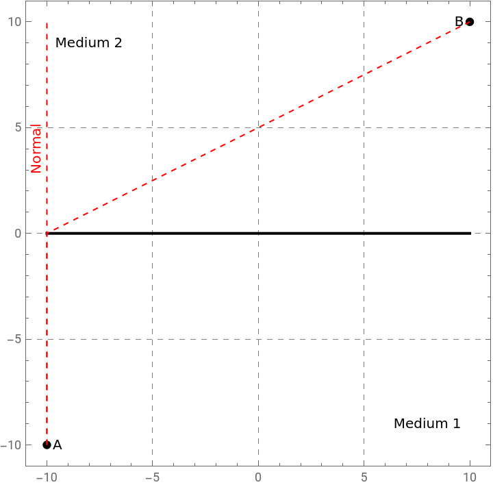
We see by manipulating the figure above, the point at which the light ray intersects the surface of interface affects how much the ray bends. When the ray intersects the surface of interface close to B or close to A, the ray bends much more than when the ray intersects the surface of interface closer to the midpoint between A and B. When the ray goes through the midpoint between these two points, the ray does not bend at all. However, light cannot follow all of these paths, as certain principles must be followed.
Solving for the allowed ray of light
Solving for the allowed ray of light
The above figure does not fully represent how a ray of light travels between points A and B because there is only one path a ray of light can take between two points. In order to complete this picture, we need to obtain a specific value for . This can be determined in a couple of ways. First, we know that the path of a ray of light is extremal. This means that the optical distance from point A to point B will become an extremal path for the correct value of .
x
x
Let us begin by calculating the Euclidean optical path between points A and B.
To find the distance light travels in vacuum, we multiply the speed of light c by the amount of time that passes Δt.
distance=cΔt
(
1
)We can write the speed of light in terms of it's refractive index with the following equation
n=
c
v
(
2
)where n is the refractive index, c is the speed of light in vacuum (in units of ), and v is the speed of light in the medium (in units of ). We can re-write equation (2) as
m
s
m
s
v=
c
n
(
3
)We then can plug v into equation (1) in place of c to find the speed of light in a medium instead of in vacuum.
distance=Δt
c
n
(
4
)Because we know that c Δt is equal to the distance from equation (1), we can re-write this equation again as
distance=Δx
1
n
(
5
)Multiplying by n, we see that Δx, or the location of x, is equal to n multiplied by the distance.
Δx=ndistance
(
6
)where distance is the Euclidean distance. We know from geometry the formula for Euclidean distance to be
EuclideanDist=+
2
(-x)
x
1
2
(-y)
y
1
(
7
)Therefore, to find the Euclidean optical path between points A and B, we will multiply the Euclidean distance in each medium with the refractive index of the medium.
In[]:=
dist[x_]:=n1++n2+;
2
(x1-x)
2
(y1-y)
2
(x2-x)
2
(y2-y)
The first derivative test from calculus tells us where we find the extremum. We can use this to determine a condition for the extremum, and set it to zero to find . Instead of performing this calculation by hand because computers do these methodical calculations much quicker, we use code to calculate the derivative with respect to x. To do this in code, we must input the command in a way the Wolfram Language can understand. The function D takes the derivative of the function, in this case dist[x], with respect to the specified variable, x. We use the double equal sign to signify that the derivative equals zero. We then set this quantity equal to condition to make it easier to use in future steps.
x
In[]:=
condition=D[dist[x],x]0
Out[]=
--0
1.5(-10-x)
100+
2
(-10-x)
1.3(10-x)
100+
2
(10-x)
We can solve the above equation represented by condition for by using the Solve function.
x
In[]:=
xval=x/.Solve[condition,x][[1]]
Out[]=
-1.40752
Let us now check if this value of is correct, by checking if Snell’s law is satisfied! This will entail constructing sines of the angles in the two media. θ1 is the angle of incidence in medium 1 and θ2 is the angle of refraction in medium 2.
x
In[]:=
sθ1=+;sθ2=+;
x-x1
2
(x1-x)
2
(y1-y)
x2-x
2
(x2-x)
2
(y2-y)
From Snell’s Law, we know that
n
1
n
2
(
8
)Therefore, we know that Snell’s law is satisfied if equation (9) is true.
n
1
n
2
(
9
)We verify this with the following code.
In[]:=
(n1sθ1-n2sθ2)/.{xxval}
Out[]=
0.
Since we have determined the value of , we may now modify our plot to add the correct light ray path in solid blue (normal in dashed blue).
x
In[]:=
DynamicModule{},LabeledManipulateGraphicsDisk[#,0.2]&/@{{x1,y1},{x2,y2}},{Thick,Line[{{x1,y},{x2,y}}]},{Red,Dashed,Line[{{{x1,y1},{x,y},{x2,y2}},{{x,y1},{x,y2}}}]},Thick,Blue,Line[{{x1,y1},{xval,y},{x2,y2}}],Dashed,Line[{{xval,y1},{xval,y2}}],RotateText["Normal",{xval-0.5,4}],,{Text["Medium 1",{8,y1+1}]},{Text["Medium 2",{-8,y2-1}]},Red,RotateText["Normal",{x-0.5,4}],,{Text["A",{x1+0.5,y1}]},{Text["B",{x2-0.5,y2}]},FrameTrue,GridLinesAutomatic,GridLinesStyleDirective[Gray,Dashed],PlotRange{{x2+1,x1-1},{y2+1,y1-1}},{x,x1,x2},"Figure 2: Possible and allowed light ray paths. The red line shows the possibilities for the paths that the ray of light might take. Not all of these paths are possible because they do not all satisfy Snell's Law. The blue line shows the actual path the light ray takes based on the principle that light travels along the path that takes the least amount of time. The blue path satisfies Snell's Law.",SaveDefinitionsTrue
π
2
π
2
Because the difference in indices of refraction is modest, the blue line showing the allowed path of the light ray intersects the surface of interface close to the midpoint. The index of refraction of Medium 2 is less than that of Medium 1, which causes the angle of refraction to be smaller than the angle of incidence and the light to bend towards the normal line. Therefore, we see that the ray of light intersects the surface of interface further from B than A. The larger the difference in the indices of refraction between the two media, the more the light ray will bend and the closer the intersection point on the surface of interface will be to either point A (if the index of refraction of Medium 1 is greater than that of Medium 2) or to point B (if the index of refraction of Medium 2 is greater than that of Medium 1).
Creating the final figure
Creating the final figure
Manipulating the final figure
Manipulating the final figure
Let us now manipulate the final figure by changing the input values. nA is the refractive index of medium 1 and nB is the refractive index of medium 2. (xA, yA) and (xB, yB) are the Cartesian coordinates of the points in medium 1 and medium 2, respectively. The y-value of the surface of interface between the two mediums is yint. We can adjust the variable’s values by adjusting the slider next to the graphic that is output. This will show us how each variable affects the ray of light passing from one medium to another.
From this diagram, we can see that when points A and B have the same x-position, the light ray follows the path of the normal line and does not bend. When the index of refraction of Medium 1 is equal to the index of refraction of Medium 2, the angle of incidence (or the angle between point B and the normal line) is equal to the angle of refraction (or the angle between point A and the normal line). In this scenario, the light ray does not bend when passing through the surface of interface, but does not necessarily follow the path of the normal line.
We can also adjust the diagram to show how light bends when moving between mediums with different indices of refraction. When light moves from high index of refraction to low index of refraction, the ray bends away from the normal. From this, we also can see that going from low index of refraction to high index of refraction bends the light towards the normal.
Apparent fish in a pond
Apparent fish in a pond
Now that we understand how ray diagrams work for refraction from a single surface, let us use this to figure out a way to find the apparent image of a fish in a pond for an observer. We will allow great freedom to the observer: variable height, position, and eye aperture. However, we will fix the fish position and the pool depth. Also, since this is a standard pool of water, the refractive indices of the media are also going to be fixed.
We acknowledge that the observer’s ability to view the fish from any position without adding an additional medium is not necessarily realistic. However, we assume that the fish can be viewed from any position, including directly above, for the purposes of showing the light ray’s path and finding the apparent position of the fish.
Position of the fish, the pool surface, and refractive indices
Position of the fish, the pool surface, and refractive indices
The first ray of light
The first ray of light
The dashed apparent ray under water is an extension of the straight line from the observer to the point the surface of interface is intersected, as seen in the figure above. This line is straight because the human eye perceives light to travel in a straight line. This causes the actual position of an object, such as a fish, to be different from the apparent position of the same object. The values of the indices of refraction of the media determine if the apparent position of the object is closer to, as in this case, or farther from the observer. Because light bends toward the normal line when going from low index of refraction to high index of refraction, the apparent position of the fish is closer to the surface than the actual position of the fish.
The second ray of light
The second ray of light
The fish appears to be located at the point where the two dashed lines intersect each other in the water. Adjusting the distance between the two light rays and the observer’s position above, we can see how the apparent position of the fish changes even though the actual position of the fish does not change.
Notice that manipulating the figure while the eye aperture is not equal to 0 causes the apparent position of the fish to change in both the x-direction (horizontal position) and y-direction (depth). This multi-directional change can be observed because of the second light ray, which is determined based on the eye aperture. Changing the eye aperture also plays a role in the apparent position of the fish. Greater eye aperture makes the fish's apparent position further from the observer in the x-direction and deeper into the pool of water.
When the observer’s x-position is moved closer to the position of the fish, the apparent position gets closer to the actual position of the fish both in the x-direction and y-direction. Moving the x-position of the observer further from the fish causes the apparent position to be closer to the surface and closer to the observer. When the observer’s height gets larger, the fish also appears closer to the actual position of the fish in both the x-direction and y-direction. As the height gets smaller, the apparent position of the fish moves closer to the surface of the water and towards the observer in the x-direction.
Refraction with 2 surfaces
Refraction with 2 surfaces
We can now build upon the techniques used in single surface refraction above to explore refraction with two surfaces. Again, consider the object to be at point A. We consider the observer to be at point C.
Defining points A and C, and the surfaces of interface
Defining points A and C, and the surfaces of interface
We leave the indices of refraction as variables.
Drawing possible rays
Drawing possible rays
We will create a figure below using Graphics that shows the possible paths of the light ray between points A and B. We draw potential ray paths between points A and B using a red line that can be manipulated by changing the locations of the points of refraction on the first and second surfaces of interface given by its x-coordinates x and x2, respectively. At the points of refraction, we include a red dashed normal line. Using the If statement, we ensure that the light ray intersects the interface between the first medium and second medium before it intersects the interface between the second medium and third medium and that the this second intersection is before the position of the observer. If these conditions are not met, there is no image produced for the observer, so we display No Image using Text. We set the options Frame to True and GridLines to Automatic, then use the directive for GridLinesStyle to produce dashed gray lines. We define PlotRange to ensure that points A and B are included in the figure. We can then manipulate the values of x and x2 to trace out different ray possibilities.
By manipulating Figure 1, we see that the amount the light ray bends is determined by where the light ray intersects the surfaces of interface. When the ray intersects the surface of interface close to B or close to A, the ray bends much more inside the second medium than when the ray intersects both surfaces of interface closer to the midpoint between A and B. However, a light ray cannot follow all of these paths because certain principles must be followed.
Solving for the allowed ray of light with 2 surfaces of interface
Solving for the allowed ray of light with 2 surfaces of interface
Therefore, to find the Euclidean optical path between points A and B, we will multiply the Euclidean distance in each medium with the refractive index of the medium.
To store these values in usable variables, we evaluate the following.
From Snell’s Law, we know the following relationship.
We must ensure Snell's Law is satisfied for all three relationships: between media 1 and 2, between media 2 and 3, and between media 1 and 3. Therefore, Snell's Law is satisfied between media 1 and 2 if
Similarly, Snell's Law is satisfied between media 2 and 3 if
To check that Snell's Law is satisfied overall, we can compare media 1 and 3 as follows.
We do this in code for each relationship as follows. Since we numerically solved the system to find the values for x and x2, we use Chop to eliminate the small decimal values from the rounding error.
Creating the final figure
Creating the final figure
We use the ideas from the code above to do all these calculations within one line of code by using Module. As we no longer need the manipulable lines showing potential ray paths, we leave out the if statements and the portion of the code that draws the red lines in drawing the final figure.
We display the figure we defined in the code above by assigning specific values to the indices of refraction of each medium and the thickness of medium 2.
We can now manipulate this figure to change the indices of refraction of the three media.
Manipulating the final figure with 2 surfaces of interface
Manipulating the final figure with 2 surfaces of interface
Let us now manipulate the final figure by changing the input values. We use Manipulate to do this and specify a range within which we want our variables to stay.
Apparent fish in a tank
Apparent fish in a tank
Now that we understand how ray diagrams work for refraction with 2 surfaces, let us use this to figure out a way to find the apparent image of a fish in a tank of water for an observer. We will allow great freedom to the observer: variable height, position, and eye aperture. However, we will fix the fish position and the location of the tank’s inner surface. Also, since this is a standard tank of water, the refractive indices of the media are also going to be fixed.
Position of the fish, the tank’s inner surface, and refractive indices
Position of the fish, the tank’s inner surface, and refractive indices
The first ray of light
The first ray of light
We draw the first ray of light similarly to that in the application where we drew the fish in a pool of water, but we use the concepts from the final figure of the 2-surface refraction. We must add the slope variable for when determining the apparent light ray because, to an observer, light appears to travel in a straight line. Therefore, we find the slope of the line segment from the observer to the point where the light ray intersects the surface of interface between glass and air. We then use this slope to extend the light ray as a dashed line to show the apparent position by taking the x-value to be the same as the actual x-value of the fish and calculating the y-value in terms of the slope.
We add Manipulate to adjust the x-value of the position of the observer, the height of the observer, and the thickness of the glass.
This apparent ray does not tell us the exact apparent position of the fish. This single ray only tells us that the apparent position of the fish lies somewhere on that line. To determine the location of the apparent fish, we need to add a second ray of light.
The second ray of light
The second ray of light
The fish appears to be at the point where the two dashed lines intersect each other in the water. Adjusting the distance between the two light rays and the observer’s position above, we can see how the apparent position of the fish changes even though the actual position of the fish does not change.
Notice that manipulating the figure while the eye aperture is not equal to 0 causes the apparent position of the fish to change in both the x-direction (horizontal position) and y-direction (depth). This multi-directional change can be observed because of the second light ray, which is determined based on the eye aperture. Changing the eye aperture also plays a role in the apparent position of the fish. Greater eye aperture makes the fish's apparent position further from the observer in the x-direction and deeper into the tank of water. We also see that when the thickness of the glass tank increases, the fish appears to be closer to the glass and closer to the observer in the x-direction.
When the observer’s x-position is moved closer to the position of the fish, the apparent position gets closer to the actual position of the fish both in the x-direction and y-direction. Moving the x-position of the observer further from the fish causes the apparent position to be closer to the glass and closer to the observer. When the observer’s height gets larger, the fish appears closer to the actual position of the fish in both the x-direction and y-direction. As the height gets smaller, the apparent position of the fish moves closer to the glass and towards the observer in the x-direction.
Acknowledgements
Acknowledgements
The work of A.H. was supported by a Student Research Award funded by the Howard Hughes Medical Institute (HHMI) Inclusive Excellence 2017 Grant to Lawrence Technological University. A.H. thanks Dr. George Moschelli for his guidance in how to determine the path of light through multiple media and for asking about the distance of a fish from its tank given the apparent position. This question led to the creation of this computational essay.
References
References
[1] S. Wolfram, “What is a Computational Essay,” Stephen Wolfram Writings (2017), available on the web at https://writings.stephenwolfram.com/2017/11/what-is-a-computational-essay/