


PDE Workflows in Mathematica That Scale with Your Team
PDE Workflows in Mathematica That Scale with Your Team
Safi Ahmed, School of Mechanical and Manufacturing Engineering, NUST, Pakistan
#WolframTechConf
ABSTRACT
ABSTRACT
The talk offers a PDE modeling pattern that can cut development time and lower onboarding costs for engineering and research teams using Mathematica.
Attendees receive ready-to-use notebooks they can adapt to their own simulations in areas like thermal systems, porous media, and biomedical flows.
Consider this PDE modeling challenge
Consider this PDE modeling challenge
If you are in an engineering org or team involved in computation, you will note that not all parts of your model follow the same physics
Fuelfiltersystem(withvalve-controlledoutlet) | Heatflowacrossanautomotiveradiator | Intertitialflowinhumanliver |
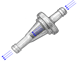
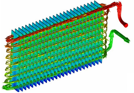
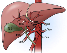
If different parts of your system follow different physical laws,
no single PDE can capture it all.
If different parts of your system follow different physical laws,
no single PDE can capture it all.
If different parts of your system follow different physical laws,
no single PDE can capture it all.
What NDSolve Can (and Can’t) Do
What NDSolve Can (and Can’t) Do
WhatNDSolvedoeswell Whereitgetstricky -NDSolvehandlesuniformphysicsbeautifully -If[...]statementsflyingeverywhere-Boundaryconditionsgetcomplicated
WhatNDSolvedoeswell | Whereitgetstricky |
| |
-NDSolvehandlesuniformphysicsbeautifully | -If[...]statementsflyingeverywhere-Boundaryconditionsgetcomplicated |
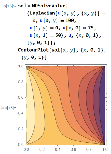
Things get messy fast when:
Your model needs more than one PDE, or
There are different PDEs governing different regions of your system
What If You Could Model Smarter (and Not Harder)?
What If You Could Model Smarter (and Not Harder)?
PDE Components:
PDE Components:
Wolfram Language has built-in PDE components (like FluidFlowPDEComponent and HeatTransferPDEComponent).
A PDE component related to your problem may not yet exist in Wolfram Language.
However, it does not mean that your problem not be modeled using Wolfram Language (you could explicitly write down your PDE model)
You can instead define a custom PDE component that makes your code more modular.
This modularity:
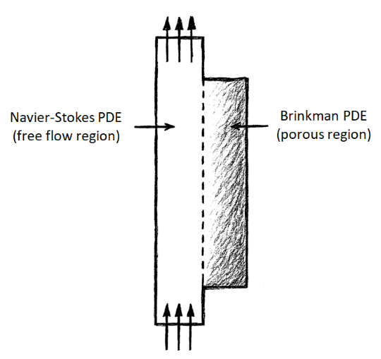
Allows for a very elegant model for a complex system e.g. Navier-Stokes PDE for free flow and Brinkman PDE for porous flow
Makes your code scalable to further problems (and facilitate reuse)
This Modeling Strategy Applies Across Domains
This Modeling Strategy Applies Across Domains
In each of these examples, different regions obey different physics. The challenge is the same: how do we model them in a way that is elegant and adaptable for teams?
In each of these examples, different regions obey different physics. The challenge is the same: how do we model them in a way that is elegant and adaptable for teams?
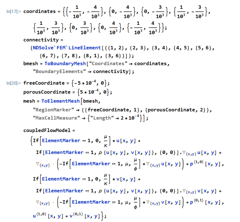
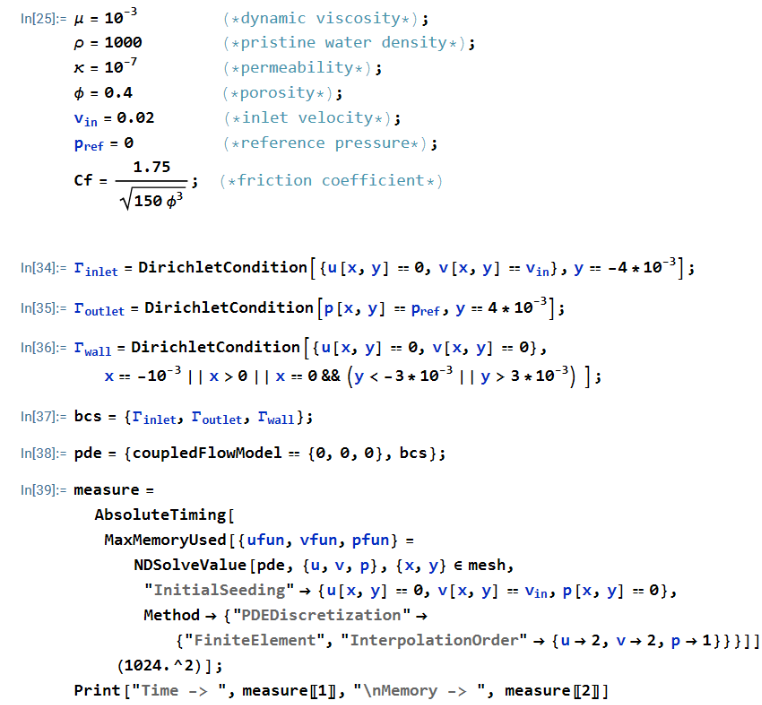
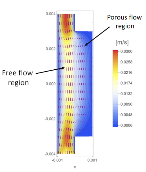
How it Looks Like in Action
How it Looks Like in Action
Note:
Note:
Explicitly used Navier–Stokes for the free flow region, Brinkman for the porous region
The model works, but the code isn’t modular -- If[...] statements flying everywhere
Consequence:
Consequence:
If I want to scale this model
to share it with a colleague
to reuse in a different project
or even to extend this PDE model within the same project
...it won’t scale well
Experimenting with Different Modeling Approaches
Experimenting with Different Modeling Approaches
Approach 1. What if we replace the manual Navier–Stokes equations with the built-in FluidFlowPDEComponent
A good thing to note:
A good thing to note:
How we have defined the physical quantities
Since it now uses the built-in components of Mathematica (optimized by the team of experts at Wolfram Research), the speed is rarely a concern.
The code is not only shorter and easier to read,
but also cleaner and ready to scale
to new projects,
to new team members (and existing ones),
to supervisors...
The code is not only shorter and easier to read,
but also cleaner and ready to scale
to new projects,
to new team members (and existing ones),
to supervisors...
but also cleaner and ready to scale
to new projects,
to new team members (and existing ones),
to supervisors...
However, we also note:
However, we also note:
Our model has two different PDEs
Approach 2. Enter BrinkmanPDEComponent...
The idea
The idea
The PDE component we built
The PDE component we built
The resulting code (comparison)
The resulting code (comparison)
Note:
Note:
Numerical inconsistencies at the interface
Likely due to structural differences between the built-in and the custom component
However, the solution
is stable,
converges well, and
remains insightful for practical use.
While demonstrated in a straight channel, this pattern could extend to more general geometries.
Ready-to-Use Tools
Ready-to-Use Tools
Tier 1 : Core components (paclet-style bundle)
Tier 1 : Core components (paclet-style bundle)
Tier 2: Create your own...
Tier 2: Create your own...
Tier 2: Create your own...
The Tier 1 bundle offers a clean starting point for those interested in creating models in their domains
The Tier 1 bundle offers a clean starting point for those interested in creating models in their domains
Heat exchanger 🌡
Filter system 🧪
Tissue scaffold 🧬
This Modeling Pattern Scales with People
This Modeling Pattern Scales with People
What this means:
What this means:
The student or team member working on this model, if they graduate or leave, the model won’t walk out with them
If you need to onboard a new person into a working simulation, you do that in days and not weeks
Finally, this way of coding means you spend less time debugging, and more time discovering 💡
I’d Love to Hear What You’re Working On
I’d Love to Hear What You’re Working On
If this talk sparked something for you, I’d love to hear about it!
🌐Presentation materials: safiahmed.me/#wtc25
Thank you for being here!
I’m happy to keep the conversation going in QnA and the various Office Hours
I’m happy to keep the conversation going in QnA and the various Office Hours